User Manual - ePowerControl
ePowerLog Series
Product installation instructions for:
- ePowerControl DL 500
- ePowerControl DL 1000
- DL 3000 & DL 10 000
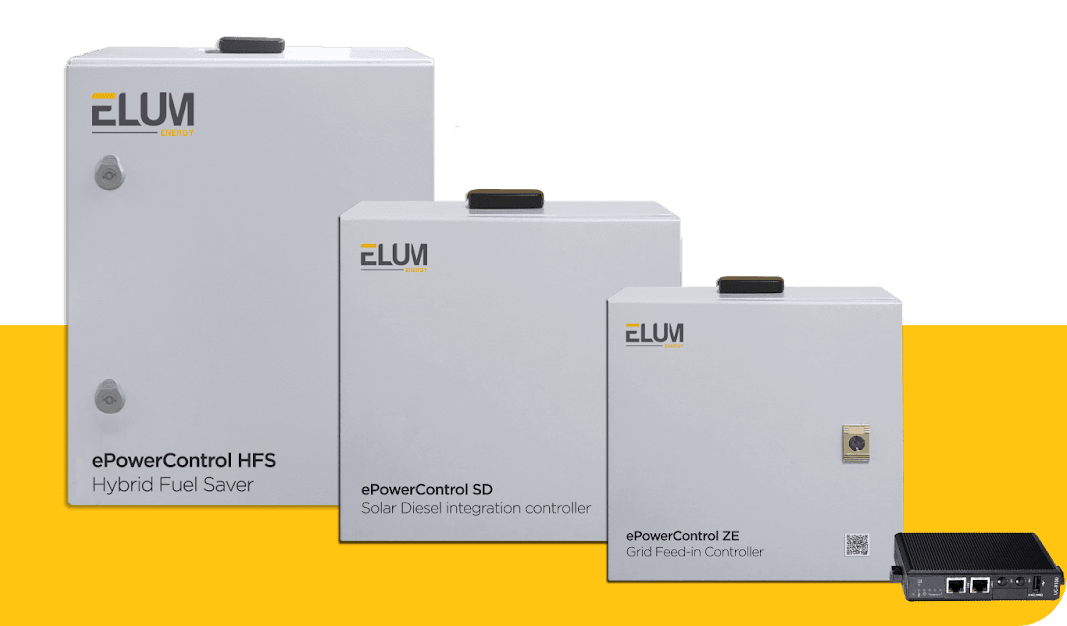
Table of Contents
General information
About this manual
This manual provides users with all the essential information needed to install, configure, and operate the ePowerLog DataLogger by Elum Energy. It covers product details, safety precautions, installation steps, and configuration guidelines.
For information on other models such as ePowerControl ZE, ePowerControl SD, ePowerControl HFS, and ePowerControl EV please refer to their respective user manuals. For ePowerControl MC and ePowerControl PPC, please contact the Elum team for assistance.
Intended audience
- EPCs involved in the deployment of new hybrid PV/Genset systems or grid-tied PV systems.
- EPCs integrating PV/Genset solutions into existing genset-based power systems.
- Professionals responsible for the design, installation, and maintenance of hybrid power systems.
To improve readability and emphasize critical information, this manual uses the following symbols:
Warning
Indicates a potentially hazardous situation that could lead to serious injury or death. This symbol is used to highlight precautionary measures and safety guidelines that must be followed.
ℹ️️ Notes
Provides general information or useful tips to help the user during installation, configuration, or operation.
⚠️ Before installing the ePowerLog, carefully read this manual to prevent personal injury and avoid equipment damage.
Glossary
| APN address | A gateway that connects a GSM, GPRS, 3G, or 4G mobile network to another computer network. |
| AWG (12 wires) | American wire gauge : A standard unit for measuring the diameter of electrical wires. |
| CT | Current Transducers: A device that detects electric current in a wire and generates a proportional signal. |
| DHCP mode | Dynamic Host Configuration Protocol: A network protocol that automatically assigns IP addresses to devices. |
| DIN rail | A standardized metal rail used for mounting industrial control equipment inside enclosures or racks. |
| EMS | Energy Management System A system designed to monitor and/or control, and optimize energy usage in industrial and commercial environments. |
| EPC | Engineering, Procurement & Commissioning : A company responsible for the design, procurement, and installation of power systems. |
| I/O module | Input/Output module : A device that manages input and output signals between control systems and external devices. |
| ICMP | Internet Control Message Protocol : A network protocol used for diagnostic and error reporting in IP networks (e.g., Ping command). |
| LAN ports | Local Area Network : Physical connections for networking devices within a local network. |
| Local NEC rules | National Electrical Code: A standard for the safe installation of electrical wiring in various regions. |
| Modbus RTU | Communication protocol to connect a supervisory computer with a remote terminal unit (RTU) |
| Modbus TCP | Communication protocol to connect a supervisory computer with a remote terminal unit through Ethernet with a transmission control protocol (TCP) |
| OCPP | Open Charge Point Protocol for communication between electric vehicle charging stations and a central management system |
| RS-485 | Standard electrical characteristics of drivers and receivers in serial communications systems |
| SCADA | Supervisory control and data acquisition |
| SNMP | Simple Network Management Protocol (SNMP) is an Internet Standard protocol for collecting and organizing information about managed devices on IP networks and for modifying that information to change device behavior. |
| UDP ports | Ports for User Datagram Protocol |
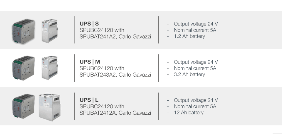
| UPS | Uninterruptible Power Supply : A backup power system used to ensure continuous operation of the controller, preventing data loss or system shutdowns during power outages. |
Legal information
Elum SAS, headquartered at 9 rue d’Enghien – 75010 Paris, is registered with the Paris Trade and Companies Registry under number 817 860 083. The company specializes in the integration and distribution of monitoring and control panels for photovoltaic and hybrid energy systems, marketed under the brands “ePowerLog” and “ePowerControl”.
Elum ensures that its controllers and dataloggers comply with French quality standards, are designed and assembled in France, and meet all necessary technical and quality requirements.
Elum reserves the right to modify the content of this document as needed. In the event of any discrepancy between translated versions, the English version shall take precedence.
Safety warnings
The ePowerLog products are electrical devices and should only be installed and operated by qualified personnel who are aware of the associated safety risks.
⚠️ Installation of meters
Voltage-carrying parts. Risk of heart attack, burns and other injuries. Disconnect the power supply and charge the device before installing the analyzer. Protect the terminals with covers. The energy analyser must be installed by qualified/approved personnel.
⚠️ Dangerous voltage
Do not touch the terminals for voltage and current measurement. Always connect grounding terminals. Do not disconnect the controller CT terminals. Be careful to protect the unit from electrostatic discharges during the installation.
ℹ️️ Internet access
A stable internet connection is required for the proper commissioning and operation of the ePowerLog.
ℹ️️ Monitoring and control features
Elum can only guarantee the monitoring and control of the site according to its product features once all of the equipment to be monitored have correctly been configured and connected to the datalogger.
Scope of supply
The ePowerLog datalogger
The ePowerLog datalogger is a ready-to-use solution that consists of a Central Computing Unit (CCU) and one or more satellites. The central unit is dedicated to data acquisition and enabling remote communication with the Elum cloud via the Internet. Any additional options purchased by the client will already be integrated into the base station, ensuring seamless operation upon installation.
ℹ️️ For detailed specifications and technical information regarding the Central Computing Unit, please refer to the ePowerLog datasheet.
Additional equipment
Additional external equipment, such as weather sensors, I/O modules, and power meters, included in the purchase order will be delivered under the same terms as the controller. Some of these components may already be pre-installed within the ePowerLog cabinet, while others will require installation by the client. For further details on optional accessories and configurations, please refer to the Options section of this manual.Monitoring platform – ePowerMonitor
Upon purchase of a subscription to the ePowerMonitor platform, and once all hardware components are installed, the internet connection is configured, and the commissioning tests are completed, Elum will provide the client with access credentials for the ePowerMonitor online platform. This access includes a User ID and Password, enabling remote monitoring and control of the system.Commissioning overview
Before proceeding to the commissioning
Before initiating the commissioning process, Elum will provide the following essential
documents:
- User Manual
- Datasheet
- Software delivery note
The ePowerLog datalogger is delivered with pre-installed Elum firmware, ensuring that it is ready for installation. The installation team must follow the step-by-step instructions provided in this manual to complete the autonomous commissioning of the datalogger.
The entire system configuration can be performed on-site, and all necessary setup details are included within this document.
ℹ️️ Equipment first integration by Elum
For the integration of new equipment by Elum, the Operations team must be notified at least 15 days prior to deployment. Failure to do so may result in limited availability of Elum engineers for assistance, and their full support cannot be guaranteed.
⚠️ PV injection precaution
During the deployment process, PV injection must remain shut down. Elum cannot be held responsible for any damage caused by uncontrolled PV injection during the commissioning process. It is the responsibility of the installation team to ensure that proper precautions are taken before proceeding.
Deployment steps
| Step 1 | Read the User Manual |
| Step 2 | Plan the communication architecture |
| Step 3 | Wire the slave devices |
| Step 4 | Connect and configure all non-Elum equipment:
|
| Step 5 | Wire and install the ePowerLog |
| Step 6 | Configure the ePowerLog online with Elum Configuration:
|
| Step 7 | Start the Data acquisition |
| Step 8 | (Optional) access to ePowerMonitor |
Step 2: Communication Architecture Plan
Objectives
Before commissioning, a clear communication plan must be established to prevent any network-related issues. The design of the network should take into account wiring limitations, communication protocol compatibility, and the configuration requirements of each device to ensure seamless integration.
RS485 Constraints: Configuring Slave ID Addresses
To ensure stable communication via RS485 (Modbus RTU), the following rules must be followed:
ℹ️️ Each device must have a unique Slave ID to avoid address conflicts.
ℹ️️ All devices connected to the same serial port must use the same communication protocol and have matching parameters, including baud rate, parity, byte size, and stop bits.
ℹ️️ The Modbus RTU protocol allows up to 32 devices to be connected to a single serial communication port.
ℹ️️ Limits
The maximum cable length for RS485 communication must not exceed 1000 meters to ensure signal integrity.
Ethernet Constraints: Configuring IP Addresses
For proper Ethernet communication, the following guidelines must be observed:
ℹ️️
- Each device must have a unique IP address within the network.
- All devices must be within the same subnet as the Elum Explorer to allow seamless data exchange.
- The subnet range 192.168.4.XX is reserved for LAN port 2 for DL 500 and DL 1000 and LAN port 4 for DL 3000 and DL 1000° and must not be used for other devices.
ℹ️️ All devices should be configured with the Subnet Mask: 255.255.255.0 to maintain proper network segmentation and communication stability.
ℹ️️ Limits
The maximum Ethernet cable length must not exceed 100 meters to prevent signal degradation and ensure reliable communication
Example
Table 1: Communication Architecture Plan Example
| Slave Reference | Slave Reference | Protocol | Slave IP address | Slave ID | Byte Size | Stop Bit | Parity | Stop Bit |
| Inverter n°1 | SMA STP 25000 TL | Modbus TCP | 192.168.3. 200 | – | – | – | – | – |
| Inverter n°2 | SMA STP 25000 TL | Modbus TCP | 192.168.3. 201 | – | – | – | – | – |
| Inverter n°3 | SMA STP 25000 TL | Modbus TCP | 192.168.3. 202 | – | – | – | – | – |
| Inverter n°3 | SMA STP 25000 TL | Modbus TCP | 192.168.3. 203 | – | – | – | – | – |
| Grid Meter | EM330-DIN .AV5.3.H.S1. X, Carlo Gavazzi | Modbus RTU | – | 2 | 9600 | 8 | No | 1 |
| Load Meter | EM330-DIN .AV5.3.H.S1. X, Carlo Gavazzi | Modbus RTU | – | 1 | 9600 | 8 | No | 1 |
Step 3: Wire the slave devices
Connecting RS485 Devices
To enable the ePowerLog to monitor external devices via RS485, a physical connection must be established. The ePowerLog functions as the master of the communication bus, while all connected equipment act as slaves. Each slave device must be properly configured to ensure seamless communication using the Modbus RTU/TCP protocol.
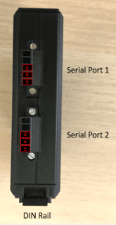
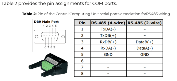
Central Computing Unit serial ports
a.) DL 500 & DL 1000
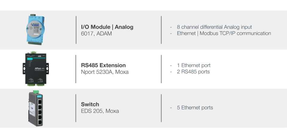
RS485-compatible devices can be connected to Serial Port 1 or Serial Port 2 on the DL 500 and DL 1000 Central Computing Unit using shielded twisted pair connectors. If an RS485 Extension Module is provided by Elum, its serial ports 1 or 2 can also be used for device connections.
For specific wiring and configuration details related to third-party hardware, please refer to the manufacturer’s documentation to ensure compatibility and correct setup.
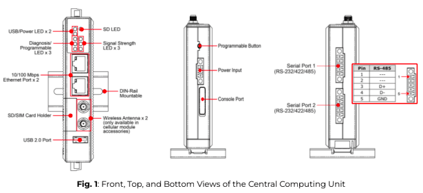
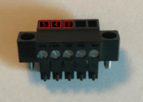
The table below provides the pin configuration for the UC-8100 (DL 500 & DL 1000) communication ports, used to connect RS485-compatible devices to the ePowerLog Central Computing Unit. Proper wiring and adherence to these pin assignments are crucial to ensure stable data transmission and device monitoring
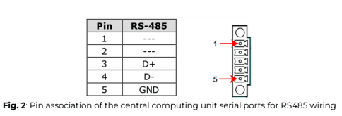
ℹ️️ For correct RS485 wiring, ensure that Pin 3 (Data B+) and Pin 4 (Data A-) are connected using a shielded twisted pair cable to prevent interference. Pin 5 (GND) should also be connected to maintain signal integrity.
If additional RS485 expansion modules are used, follow the same pin configuration for serial communication. For third-party devices, refer to their respective technical documentation to verify compatibility with the UC-8100 (DL 500 & DL 1000) communication ports.
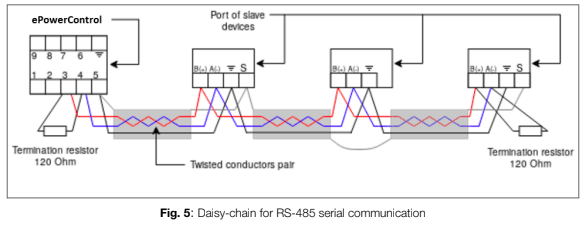
b.) DL 3000 & DL 10 000
Compatible RS485 devices can be connected to any of the four serial ports available on the DL 3000 and DL 10000 Central Computing Unit. This connection must be made using two shielded twisted pair connectors to ensure proper data transmission and minimize electromagnetic interference.
If an RS485 Extension has been provided by Elum, any available serial port on the extension can also be used for connecting RS485 devices.
For detailed configuration and installation guidelines specific to third-party hardware, please refer to the manufacturer’s documentation.

RS-485 wiring guidelines
Proper wiring of the RS-485 serial line is essential for ensuring reliable data
transmission between the ePowerLog and connected devices.
Follow these guidelines to minimize interference and maintain stable
communication:
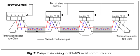
- Daisy chaining connections
1. Pin 3 (DataB +) of the serial port should be connected in a daisy-chain with all DataB (+) ports of the connected devices
2. Pin 4 (DataA -) of the serial port should be connected in a daisy-chain with all DataA (-) ports of the connected devices.
3. Pin 5 (GND) should be connected in a daisy-chain with all GND ports of the connected devices. - Cable selection & Organization
1. Use twisted-pair cables for DataB (+) and DataA (-) to reduce electromagnetic interference
2. To simplify wiring and avoid errors, maintain a consistent color scheme (e.g., red for DataB (+), blue for DataA (-), and black for GND).
Termination of data wires
To prevent signal reflections and data errors, termination resistors must be installed:
- A 120 Ohm resistor should be placed at each end of the RS-485 communication line, connecting DataB (+) and DataA (-).
- The resistance value must be compatible with the impedance of the communication cable used.
Shielding
- It is recommended to use shielded RS-485 cables to protect against external electrical noise.
- The shielding should be continuous along the entire RS-485 communication line and must be connected to the GND (Pin 5) at the datalogger.
- To prevent ground loops, the shield should only be connected at a single point, preferably at the datalogger side.
RS-485 usage limitations:
- The total cable length between the datalogger and the farthest external device must not exceed 1 km for proper signal integrity.
- The use of unshielded cables should be minimized to prevent communication interference.
⚠️ Failure to adhere to the RS-485 wiring guidelines, including the use of termination resistors, proper grounding, and adequate shielding can lead to unstable communication, reduced performance, and even potential equipment damage.
⚠️ To maintain signal integrity, shield continuity must be ensured throughout the entire communication line. This requires dedicated third-party hardware for shield connections, with the shield being grounded at a single point to prevent ground loops.
ℹ️️ For RS-485 lines exceeding 100 meters, the installation of a 120 Ohm termination resistor is strongly recommended. This resistor should be placed between pin 3 and pin 4 on the RS-485 port of the Central Computing Unit, ensuring stable data transmission over long distances.
Connecting Ethernet Devices
To enable the ePowerLog to monitor Ethernet-based equipment, a physical Ethernet connection must be established. The ePowerLog acts as the master of the communication network, while all connected devices function as slaves. The datalogger communicates via Modbus TCP/IP.
Central Computing Unit LAN ports
To connect power units, sensors, or other Ethernet-compatible devices, use an Ethernet-male to Ethernet-male cable and connect it to the LAN ports on the ePowerLog module.
- If an Ethernet switch is not used, devices communicating via Modbus TCP should be directly connected to LAN port 1 on the DL 500 and DL 1000 (see Figure 4) or on LAN port 1, 2, 3 on the DL 3000 and DL 10000 (see Figure 5).
- If an Ethernet switch is used, all Modbus TCP devices should be connected to any of the available ports on the switch. One of the Ethernet switch ports must then be connected to the ePowerLog datalogger, ensuring seamless data transmission.

The two 10/100 Mbps Ethernet ports of the Central Computing Unit and the switches provided by Elum use RJ45 connectors.

Wiring
The wiring of the Ethernet line should be done by connecting each of the Slaves to the ePowerLog using an RJ45 cable
Wiring an AC Meter | 5A provided by Elum
Materials required
The installation and wiring of an AC Meter | 5A provided by Elum require the following components:
- Circuit protection: For each phase, use the smallest available breakers or rated fuse taps according to local NEC regulations. Typically, a 15A circuit breaker or a single multipole breaker is used, depending on the number of phases.
- Wiring: Use black, red, and white stranded AWG 12 wire, ensuring a thermal resistance of at least 75°C. The wire length should be determined based on the installation location. For three-phase installations, an additional blue wire is required. The insulation rating of the wire must be greater than the maximum voltage inside the panel.
- Other materials:
○ Electrical tape for insulation.
○ Conduit and couplings as needed.
○ Mounting and wire organization hardware to ensure a neat and secure installation.
○ Outdoor-rated enclosure (if the meter is installed outside) to protect against environmental conditions.
Safety warnings
⚠️ To ensure a safe and proper installation, always follow the wiring diagrams and CT selection guidelines provided in this manual.
To reduce the risk of electric shock and prevent damage to the equipment:
- Do not connect the device to a circuit that operates at more than 277 Vrms to neutral.
- Always disconnect circuits from the building’s power distribution system before installing or servicing the power meter or attached current transformers (CTs).
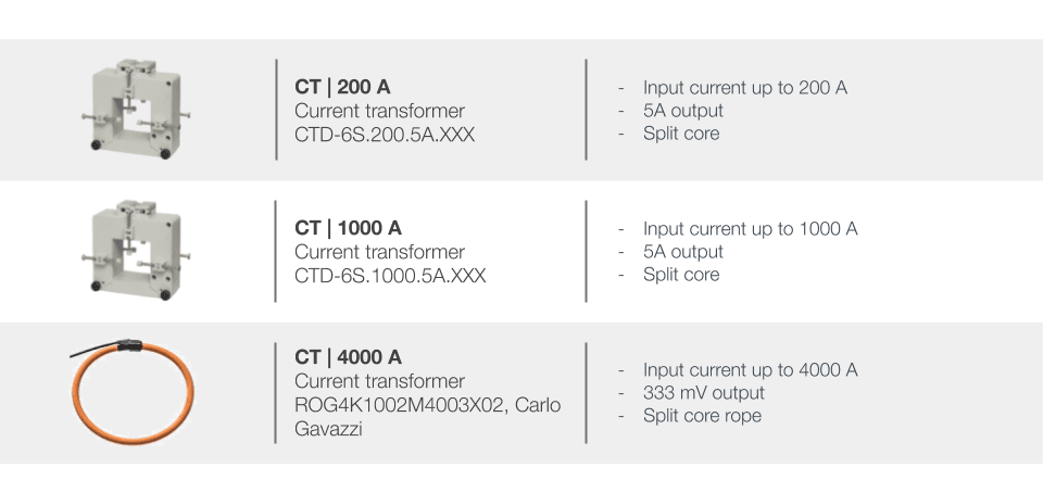
- Only use authorized 5A CTs with this device to maintain accurate measurement and ensure safe operation.
Installation location
The power meter should be installed near the low-voltage distribution panel, ensuring easy access to connections for the grid, load, and genset (refer to the application overview for guidance). A 10A circuit breaker must be installed for each phase, positioned close to the meter and within easy reach of the operator. These breakers must be clearly labeled as the disconnecting devices for the power meter to allow quick identification and access.
Since the power meter is a listed device, it must be housed inside a suitable enclosure that meets the environmental requirements of the installation site:
- For indoor installations, a standard electrical cabinet is sufficient.
- For outdoor installations, a weatherproof, outdoor-rated enclosure is required to protect against moisture, dust, and direct sunlight.
When selecting the installation location, ensure that the power meter is not exposed to direct sunlight or extreme environmental conditions.
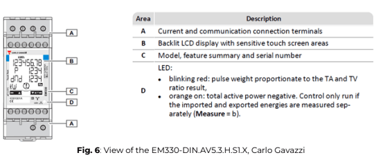
Device overview
Installation steps
- Place the required breaker(s) in the power distribution panel, ensuring access to all phases of the system.
- Open the breakers to ensure there is no power on the breaker contacts before proceeding with the installation.
- Securely mount the power meter inside a suitable enclosure near the power
distribution panel. - Ensure the enclosure is appropriate for the installation environment (e.g., outdoor-rated enclosures for external installations).
- Wiring the Power Meter and CTs:
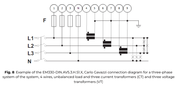
a. Follow the wiring diagram corresponding to the site’s system layout to properly connect the power meter.
b. For a three-phase system with a 4-wire unbalanced load, connect the three current transformers (CTs) as specified in the installation diagram.
c. Ensure the stickers on the CTs are correctly oriented toward the measured current flow direction to avoid incorrect readings.
d. If the CT wires need to be adjusted in length, ensure they are securely connected without compromising signal integrity.
ℹ️️ The main voltage must not exceed 400V, and the CTs must always have 5A secondary current.
ℹ️️ The power supply should be 65-400V AC, 50Hz.
⚠️ The auxiliary power supply on the meter ensures it remains powered regardless of whether the plant is running on the grid or gensets.
Power meters responsible for monitoring the grid, load, or gensets should never be turned off, as this could trigger a fail-safe mode in the ePowerLog, leading to curtailed PV production.
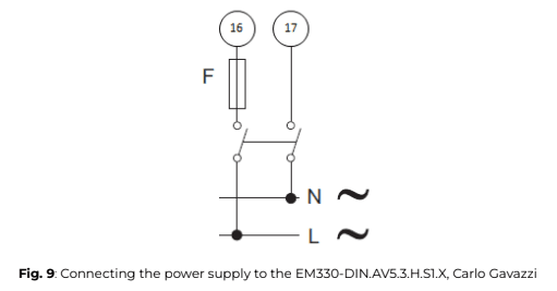
7. Close the newly installed breakers to energize the power meter. Within a few seconds, the screen should illuminate, displaying the measurement page to confirm proper operation.
8. Once the power meter is successfully powered on, you can continue with the configuration and parameter setup to align with the system’s operational requirements.
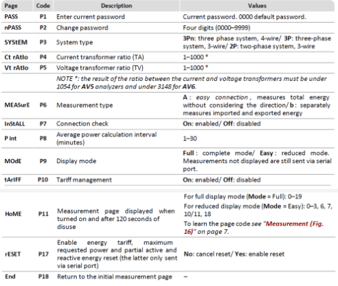
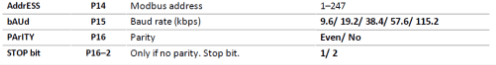
ℹ️️ After powering up the EM330-DIN.AV5.3.H.S1.X power meter, it is essential to configure its parameters correctly to ensure accurate measurements and proper system integration. Below are the critical settings that must be adjusted:
SYStEM, System type: To be set according to the site design
Ct rAtIo, Current transformer ratio: To be set according to the CTs used with the power meter. You can obtain this ratio by dividing the primary current by the secondary current. As an example, when using 200 A to 5 A CTs, the ratio should be set to 40.
Vt rAtIo, Voltage transformer ratio: To be set according to the VTs used with the power meter. You can obtain this ratio by dividing the primary voltage by the secondary voltage. As an example, when the power meter when using no VTs, the ratio should be set to 1.
MEASurE, Measurement type: To be set to “b”
AddrESS, Modbus address: To be set according to your ID plan
⚠️ The result of the ratio between the current and voltage transformers must be under 1054.
⚠️ It is critical that the measurement type was correctly set up to “b” for the zero export control feature. If the power meter was not correctly set up, Elum cannot guarantee any reliability on the zero export feature and will not be taken responsible if some energy is exported to the grid.
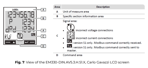
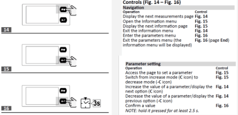
ℹ️️ Instructions to use the power meter and navigate through the different menus.
Measurement pages displayed by default when turned on. Pages are characterized by the reference unit of measure. The initial measurement page set is displayed after 120 s of disuse.
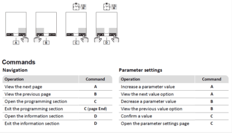
ℹ️️ Parameters description
9. Proceed to the communication wiring of the power meter as described below. Connect the power meter to one of the serial ports of the Central Computing Unit using a shielded twisted-pair RS485 connector and a Cat 5 cable.
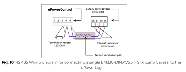
Additional RS485 power meters should be connected in parallel, with the serial output terminated only on the last device by connecting terminals B+ and T.
For connections over 1000 meters or networks with more than 160 devices, a signal repeater must be used.
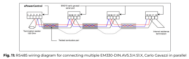
⚠️ The continuity of the shielding must be ensured throughout the communication cable, and the ground must be connected at a single point. The total length of the cable must not exceed 1000m.
10. Label the newly installed breakers as “Power Meter Disconnect” so they can be easily identified if the device needs to be power-cycled or turned off.
Wiring an AC Meter | 333mV provided by Elum
Materials required
- Circuit protection: For each phase, use the smallest available breakers or rated fuse taps according to local NEC regulations. Typically, a 15A circuit breaker or a single multipole breaker is used, depending on the number of phases.
- Wiring: Use black, red, and white stranded AWG 12 wire, ensuring a thermal resistance of at least 75°C. The wire length should be determined based on the installation location. For three-phase installations, an additional blue wire is required. The insulation rating of the wire must be greater than the maximum voltage inside the panel.
- Other materials:
○ Electrical tape for insulation.
○ Conduit and couplings as needed.
○ Mounting and wire organization hardware to ensure a neat and secure installation.
○ Outdoor-rated enclosure (if the meter is installed outside) to protect against environmental conditions.
Safety warnings
⚠️ To ensure a safe and proper installation, always follow the wiring diagrams and CT selection guidelines provided in this manual.
To reduce the risk of electric shock and prevent damage to the equipment:
- Do not connect the device to a circuit that operates at more than 277 Vrms to neutral.
- Always disconnect circuits from the building’s power distribution system before installing or servicing the power meter or attached current transformers (CTs).
- Only use authorized 5A CTs with this device to maintain accurate measurement and ensure safe operation.
Installation location
The power meter should be installed near the low-voltage distribution to ensure easy access to the grid, load, and genset connections (see application overview). A 10A circuit breaker per phase must be installed close to the device and within easy reach of the operator. These breakers must be clearly labeled as the disconnecting device for the power meter.
As a listed device, the power meter must be housed in a suitable enclosure rated for its installation environment. For outdoor installations, a weather-resistant, outdoor-rated enclosure is required to protect against environmental conditions. The installation location should be shielded from direct sunlight and harsh elements to ensure long-term reliability and accuracy.
Device overview
Installation steps
- First, install the breaker(s) in the power distribution panel, ensuring they provide access to all phases.
- Before proceeding, open the breakers to ensure no power is present on the breaker contacts.
- Next, mount the power meter inside a suitable enclosure near the power distribution panel, ensuring easy access for wiring and maintenance.
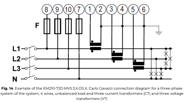
- Proceed with the wiring of the power meter and CTs, following the wiring diagram corresponding to the site system layout. For a three-phase system with a 4-wire unbalanced load, connect the three current transformers (CTs) as specified. Ensure that the CT stickers are correctly oriented toward the measured current flow. If CT wires need to be shortened or extended, make sure they are properly connected to maintain signal integrity.
ℹ️️ The main voltage must not exceed 400V, and the CTs must always have a 333mV output.
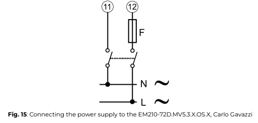
5. Proceed with the power supply wiring of the power meter as specified. The power supply should be 65-400V AC, 50Hz.
ℹ️️ The power supply should be 65-400V AC, 50Hz.
⚠️ The auxiliary power supply on the meter ensures it remains powered regardless of whether the plant is running on the grid or gensets. Power meters responsible for monitoring the grid, load, or gensets should never be turned off, as this could trigger a fail-safe mode in the ePowerControl, leading to curtailed PV production.
6. Once the wiring is complete, close the newly installed breakers. Within a few seconds, the power meter should turn on, and its screen will display the measurement page.
7. At this point, you can proceed with the parameter setup of the power meter.
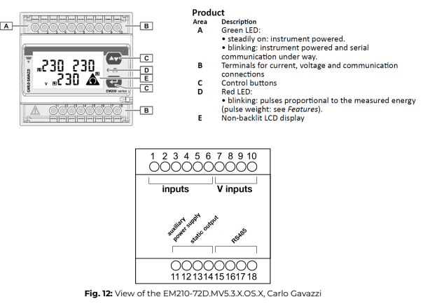
ℹ️️ When installing a EM210-72D.MV5.3.X.OS.X, Carlo Gavazzi the critical parameters to be set are listed below:
SYStEM, System type: To be set according to the site design.
SEnSOr , CT type: To be set according to the CTs used with the power meter. As an example, when installing the power meter with Rogowski coil CTs, the type should be set to roG Ct Prin, Current transformer maximum current input: To be set according to the CTs used with the power meter. As an example, when installing the power meter with Rogowski coil 4000A, the type should be set to 4,00k.
Vt rAtIo, Voltage transformer ratio: To be set according to the VTs used with the power meter. You can obtain this ratio by dividing the primary voltage by the secondary voltage. As an example, when installing the power meter using no VTs, the ratio should be set to 1.
APPLiC, Measurement application: To be set to “E”.
AddrESS, Modbus address: To be set according to your ID plan
⚠️ The combined ratio of the current and voltage transformers must not exceed 1054.
⚠️ It is essential to set the measurement application to “E” for the zero export control feature. If this setting is incorrect, Elum cannot guarantee the reliability of zero export control and will not be responsible for any unintended energy export to the grid.
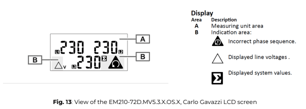
ℹ️️ For instructions on using the power meter and navigating through its menus, refer to the manufacturer’s guidelines.
When powered on, the default measurement pages will be displayed, each showing a reference unit of measure. If no interaction occurs, the initial measurement page will automatically reappear after 120 seconds of inactivity.
8. To establish communication, connect the power meter to one of the serial ports of the Central Computing Unit (CCU) using a shielded twisted-pair RS485 connector and a Cat 5 cable.
Fig. 16: RS485 wiring diagram for connecting a single EM210-72D.MV5.3.X.OS.X, Carlo Gavazzi
Additional RS485 power meters must be connected in parallel (daisy-chained). The serial output should only be terminated on the last device in the network by connecting terminals B+ and T.
The total cable length must not exceed 1000 meters to ensure reliable communication.
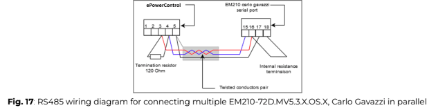
⚠️ The shielding continuity must be maintained throughout the entire communication cable, with the ground connected at a single point to prevent interference.
To facilitate maintenance, label the newly installed breakers as “power meter Disconnect” so you can easily locate them if the device needs to be power-cycled or turned off.
Step 4: Configuring non-Elum equipment
Configuring Solar Inverters
Some solar inverters may require RS485 control features to be activated. To configure a specific inverter, please refer to the manufacturer’s instructions.
The Elum ePowerLog must communicate with solar inverters to collect data for monitoring purposes. To achieve this, the datalogger interacts with the inverters to:
- Collect active power output measurements
- Communicate maximum power output setpoints
- Retrieve additional measurement data useful for monitoring operations
Table 3 lists all the accessed variables.
Table 3: Solar inverter variable accessed
| Elum Name | Description | Max Access |
| W | Total active power | Read Only |
| WphA | Active power phase A | Read Only |
| WphB | Active power phase B | Read Only |
| WphC | Active power phase C | Read Only |
| VAR | Total reactive power | Read Only |
| VARphA | Reactive power phase A | Read Only |
| VARphB | Reactive power phase B | Read Only |
| VARphC | Reactive power phase C | Read Only |
| VA | Total apparent power | Read Only |
| VAphA | Apparent power phase A | Read Only |
| VAphB | Apparent power phase B | Read Only |
| VAphC | Apparent power phase C | Read Only |
| Hz | Frequency | Read Only |
| AphA | Current phase A | Read Only |
| AphB | Current phase B | Read Only |
| AphC | Current phase C | Read Only |
| PhVphA | Line voltage phase A | Read Only |
| PhVphB | Line voltage phase B | Read Only |
| PhVphC | Line voltage phase C | Read Only |
| Status | Solar inverter status | Read Only |
| Operating Mode | Solar inverter operating modes | Read Only |
| Alarm | Solar inverter alarms | Read Only |
| WSet | Solar inverter maximum active power setpoint | Read / Write |
Table 4: Requirement for solar inverter
| RS1 | Each inverter must allow Modbus RTU or TCP communication |
Configuring Genset Controllers
To enable remote communication or activate reverse power protection on a genset controller, follow the manufacturer’s instructions.
Elum ePowerLog must communicate with the genset or its controller to ensure safe operation and collect monitoring data. To perform this task, the datalogger gathers:
- Active power output measurements
- Additional accessible data needed for site monitoring
Table 5 list all the accessed variables.
Table 5: Genset or genset controller variable accessed
| Elum Name | Description | Max Access |
| W | Total active power | Read Only |
| WphA | Active power phase A | Read Only |
| WphB | Active power phase B | Read Only |
| WphC | Active power phase C | Read Only |
| VAR | Total reactive power | Read Only |
| VARphA | Reactive power phase A | Read Only |
| VARphB | Reactive power phase B | Read Only |
| VARphC | Reactive power phase C | Read Only |
| VA | Total apparent power | Read Only |
| VAphA | Apparent power phase A | Read Only |
| VAphB | Apparent power phase B | Read Only |
| VAphC | Apparent power phase C | Read Only |
| Hz | Frequency | Read Only |
| AphA | Current phase A | Read Only |
| AphB | Current phase B | Read Only |
| AphC | Current phase C | Read Only |
| PhVphA | Line voltage phase A | Read Only |
| PhVphB | Line voltage phase B | Read Only |
| PhVphC | Line voltage phase C | Read Only |
| Status | Genset status | Read Only |
| Operating Mode | Genset operating modes | Read Only |
| Alarm | Genset alarms | Read Only |
| WSet | Gensets active power setpoint | Read / Write |
Table 6: Requirement for genset or genset controller
| RS1 | The genset or the controller must allow Modbus RTU or TCP communication |
Configuring Grid and Load Sensors
Elum ePowerLog must gather information from the Point of Connection (POC) between the site and the external power grid, as well as from the load. This data is collected using sensors that measure all required electrical parameters.
The datalogger communicates with the installed sensor to collect:
- Active power measurements
- Relevant data for system monitoring
By default, the power meters provided by Elum meet all these requirements
and will be used unless specified otherwise.
Table 7 lists all the accessed variables.
Table 7: Grid sensor variable accessed
| Elum Name | Description | Max Access |
| W | Total active power | Read Only |
| WphA | Active power phase A | Read Only |
| WphB | Active power phase B | Read Only |
| WphC | Active power phase C | Read Only |
| VAR | Total reactive power | Read Only |
| VARphA | Reactive power phase A | Read Only |
| VARphB | Reactive power phase B | Read Only |
| VARphC | Reactive power phase C | Read Only |
| VA | Total apparent power | Read Only |
| VAphA | Apparent power phase A | Read Only |
| VAphB | Apparent power phase B | Read Only |
| VAphC | Apparent power phase C | Read Only |
| Hz | Frequency | Read Only |
| AphA | Current phase A | Read Only |
| AphB | Current phase B | Read Only |
| AphC | Current phase C | Read Only |
| PhVphA | Line voltage phase A | Read Only |
| PhVphB | Line voltage phase B | Read Only |
| PhVphC | Line voltage phase C | Read Only |
Table 8: Requirement for grid sensor
| RS1 | The sensor must allow Modbus RTU or TCP communication |
Step 5: Installing the ePowerLog
Installation
ℹ️️ Installation location
The ePowerLog is designed for indoor installations. If an outdoor installation is required, a special housing must be specified when placing the order.
ℹ️️ Internet access
A stable internet connection is required for the autonomous deployment of the ePowerLog and for maintenance interventions by Elum engineers. The enclosure should be installed in a location with at least edge-level reception if using a wireless connection, or with a stable local network connection if using a wired connection.
Instructions for installing the ePowerLog when in casing
To wall mount the ePowerLog enclosure, follow these steps:
- Remove the mounting plate by unscrewing the four nuts securing it inside the enclosure.
- Mount the Base Station to the wall using the appropriate screws and wall plugs.
- Reattach the mounting plate inside the enclosure.
Instructions for installing the ePowerLog when in kit
If delivered as a kit, all ePowerLog components must be installed on a DIN rail. To prevent the Central Computing Unit from overheating, ensure a 15 cm cooling space on each side of the unit.
Power Supply
To power the electrical enclosure, use the screw terminal block. The allowed voltage range is 100 to 240V AC, with a maximum current draw of 1.30A.
ℹ️️ Power source
The power source supplying the controller must be taken from the load side to ensure it remains powered in both “On-grid” (Grid-connected mode) and “Off-grid” (Genset-connected mode)” operations.
If a UPS is used, its power source must also follow this same rule to guarantee continuous operation of the controller under all conditions.
Instructions for connecting the power supply to ePowerLog when in Elum casing
1. The power connectors are pre-wired to a single screw terminal block on the left side of the DIN rail.
Instructions for connecting the power supply to ePowerLog when in kit
a) DL 500 and DL 1000Table 9: ePowerLog Power Supply Parameters
| Input voltage | 12 to 24 VDC |
| Input Current | 480 mA @ 12 VDC 225 mA @24 VDC |
| Power Consumption | 5,4 W |

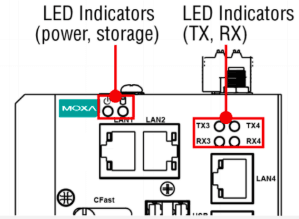
ℹ️️ When the ePowerLog is turned on, all LEDs will illuminate for 1 second, then turn off for 60 seconds while the Internet connection and system services initialize.

On the left side, LEDs for diagnosis:
– Green light (independent from orange and red lights):
- ON: The local data retrieval system is functioning properly.
- OFF: The retrieval system and/or local database are inactive.
– Orange light ON, Red light OFF:
- The connection to the Elum server is active.
– Red light ON, Orange light OFF:
- The connection to the Elum server is inactive.
– Red light BLINKING:
- The local data retrieval system is functioning, but the connection to the Elum server is not active.
On the right side, LEDs for network:
– Red light BLINKING:
- No internet connection detected.
– Green light ON, Other Lights OFF:
- Internet access via Ethernet: Connection OK.
– Red light ON, Other Lights OFF:
- Internet access via 3G, 4G, or GSM with poor reception (< 25%).
– Red and Orange lights ON, Green OFF:
- Internet access via 3G, 4G, or GSM with moderate reception (25-50%).
– Red, Orange, and Green lights ON:
Internet access via 3G, 4G, or GSM with good reception (> 50%).
b) DL 500 and DL 1000
Table 9: ePowerLog Power Supply Parameters
| Input voltage | 12 to 24 VDC |
| Input Current | 480 mA @ 12 VDC 225 mA @24 VDC |
| Power Consumption | 5,4 W |
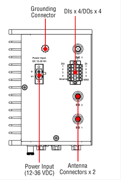
1. To power the Central Computing Unit (CCU), connect the “terminal block to power jack converter” (included in the package) to the DC terminal block located on the top panel of the unit. Then, connect the power adapter. The system will take approximately 30 seconds to boot up.
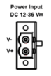
2. Proper grounding and wire routing help reduce electromagnetic interference (EMI) and ensure stable operation. The shielded ground contact (also known as protected ground) is the top contact of the 3-pin power terminal block connector. Connect the shielded ground wire to a properly grounded metal surface to enhance protection and minimize interference.
ℹ️️ When the ePowerControl is turned on, all LEDs will illuminate for 1 second, then turn off for 60 seconds while the Internet connection and system services initialize.
The central processing unit within the ePowerControl controller is equipped with multiple LED indicators that offer a quick overview of the system’s status. Their meanings are detailed in the table below.

Step 6: Configuring the ePowerLog in eConf
Before proceeding to the commissioning
Required Materials
To configure internet access, you will need:
- A computer with an Ethernet port
- An Ethernet cable
- If your computer does not have a LAN port, use a USB-to-Ethernet or Type-C-to-Ethernet adapter.
Prerequisite
Before commissioning your system, Elum may require a firmware update to ensure access to the latest version of eConf with the most recent communication drivers. Keeping the drivers updated is essential for reliable communication tests and for conducting wiring reviews and ePowerLog configuration autonomously.
Accessing eConf
2. To access eConf interface, connect your laptop to LAN2 (for DL 500 and DL 1000) or LAN4 (for DL 3000 and DL 10 000) of the Central Computing Unit (CCU).
Ensure that the CCU is powered on (check the Power LED).
3. Then, open a web browser and enter 192.168.4.127 in the URL bar to access the configuration settings.
ℹ️️ To access eConf local web page, ensure that your computer’s Ethernet port is configured in DHCP mode.
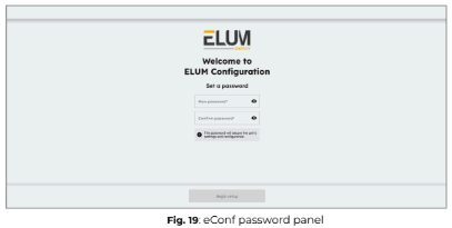
Configuring your password
On the login page, set an access password, which will be required each time you connect to the ePowerLog and access the configuration platform “eConf”. Once the password is set, click “Begin Setup” to proceed.
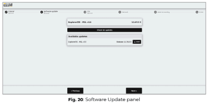
Checking and installing Software Updates
After setting up the password, the system will automatically check for available software updates and display them. However, you can also manually check for updates by clicking on “Check for updates”.
If an update is available, it will appear in the “Available updates” section. To proceed with the update, click the “Install” button. The update process will then begin, ensuring your system runs the most recent version of ExplorerOS.
It is recommended to install the latest available update to ensure optimal performance and compatibility.
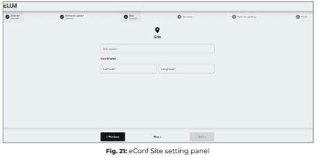
Configuring site settings (optional)
Enter the name and GPS coordinates of the site associated with the ePowerLog datalogger.
ℹ️️ The information provided in this panel will be used to configure the ePowerMonitor dashboard. Access to ePowerMonitor requires a subscription to the platform.
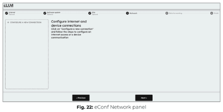
Configuring internet access (optional)
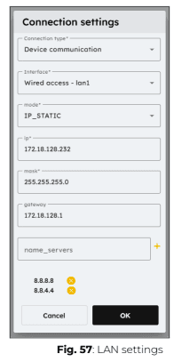
After setting up the site settings, you will need to configure the network settings for internet access and device communication.
Configuring a wired internet connection
ℹ️️ The LAN connection that allows the ePowerLog to access the internet via a wired connection must always be made through LAN port 1 for DL 500 and DL 1000 or LAN port 1, 2 or 3 for DL 3000 and DL 10000 of the Central Computing Unit (CCU). If additional LAN ports are needed, a network switch can be connected to the LAN port.
ℹ️️ To properly configure the internet connection, coordination with the IT team is essential. The following outgoing IPv4 network accesses must be allowed for the controller to communicate with the Elum backend servers:
● ICMP (Ping Protocol)
● TCP Ports: 53, 80, 443, 4505, 4506
● UDP Ports: 53, 123, 1195
Additionally, before installation, request the network configuration details that should be applied to the ePowerLog to ensure proper connectivity.
No optional module is required to establish a wired internet connection between the ePowerLog and the internet.
1. Click on “+ Configure a new connection” and select “Internet access”, then choose “Wired Access – LAN1”.
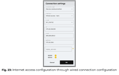
2. Enter the appropriate connection parameters based on your network settings and press OK.
3. Click the “Test” button to verify the connection. 
Configuring a cellular internet connection
ℹ️️ The GSM/3G module is pre-installed in the Central Computing Unit (CCU). However, you will need a SIM card with a valid data subscription to enable connectivity.
⚠️ The ePowerLog must be turned off before inserting or removing the SIM card.
If you need to change the SIM card, an empty start (powering on without a SIM card before inserting the new one) must be performed.
a) DL 500 and DL 1000
For these steps, the Central Computing Unit must NOT be powered on.
1. Connect the two wireless antennas to the dedicated connectors on the front panel of the CCU.
ℹ️️ The antenna connectors are located on the front Panel of the Central Computing Unit
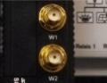
2. Insert the SIM card into the SIM card slot, located next to ports W1 and W2 for antennas.
ℹ️️ To access the SIM card slot, use a screwdriver to open the cover.
Insert the SIM card directly into the slot until you hear a “click”, indicating it is securely in place.

3. Power ON the Central Computing Unit (CCU).
ℹ️️ Upon startup, all LEDs will turn ON for 1 second, then turn OFF for 60 seconds while the system initializes.
4. Wait approximately 1 minute for the startup process to complete.
5. In the Network Configuration Panel, click “+ Configure a new connection” and select “Internet access”, then choose “3G Access – Built-in”.
6. Enter the appropriate connection parameters for your network and press OK.
7. Test the connection by clicking the “Test” button. 
b) DL 3000 and DL 10000
1. Connect the two wireless antennas to the dedicated connectors on the front panel of the CCU.
ℹ️️ The antenna connectors are located on the front Panel of the Central Computing Unit.
2. Insert the SIM card into the SIM card slot.
ℹ️️ To access the SIM card slot, use a screwdriver to open the cover.
Insert the SIM card directly into the slot until you hear a “click”, indicating it is securely in place.
3. Power ON the Central Computing Unit (CCU).
ℹ️️ Upon startup, all LEDs will turn ON for 1 second, then turn OFF for 60 seconds while the system initializes.
4. Wait approximately 1 minute for the startup process to complete.
5. In the Network Configuration Panel, click “+ Configure a new connection” and select “Internet access”, then choose “3G Access – Built-in”.
6. Enter the appropriate connection parameters for your network and press OK.
7. Test the connection by clicking the “Test” button.
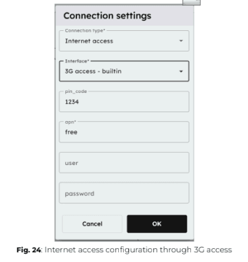
ℹ️️ To obtain your SIM card PIN number, APN address, and required credentials, please refer to the documentation provided by your service provider. These details are necessary to configure the GSM/3G connection on the ePowerLog.
Configuring ports and devices
Once the wiring and internet configuration is complete, you can proceed with setting up communication between the ePowerLog and connected devices.
From eConf you have to configure each connection corresponding to each of the ports of the Central Computing Unit which are used.
1. Click “+ Configure a new connection” and select “Device communication”, then choose the appropriate interface.
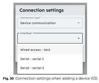
ℹ️️ Only unused interfaces will be available in the drop-down list. If a port has already been configured, you can edit its settings directly. 
2. Apply the correct connection settings based on the device requirements.

3. Once the connection is configured, add each device one by one by clicking “+ Add device”.
4. Apply the correct parameters for each device to ensure proper communication.


ℹ️️ Communication parameters
Modbus RTU:
- Slave ID: Unique identifier for the device.
- Response Timeout (default: 0.5s): Maximum waiting time before receiving the first byte of the response.
- Byte Timeout (default: 0.1s) : Maximum waiting time between subsequent bytes in the response.
Modbus TCP:
- IP Address: The device’s network address.
- Port (default: 502): The communication port used for Modbus TCP.
- Slave ID: Unique identifier for the device.
- Response Timeout (default: 0.5s): Maximum waiting time before receiving the first byte of the response.
- Byte Timeout (default: 0.1s): Maximum waiting time between subsequent bytes in the response
SNMP:
- IP Address: The device’s network address. Community: The SNMP community string for authentication.
- Port (default: 161): The communication port for SNMP.
- Transport (default: UDP): The protocol used for SNMP communication.
- Timeout (default: 0.5s): Maximum waiting time before receiving a response.
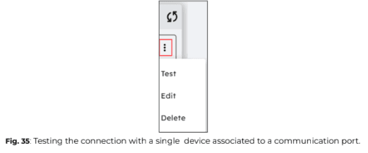
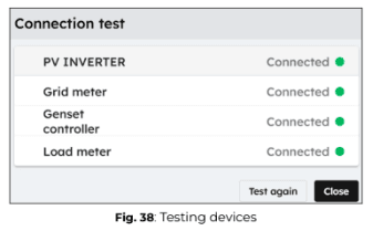
5. To test all devices linked to a specific connection port on the Central Computing Unit (CCU), click on “Test” in the connection settings. 

To test a single device independently, click on the three dots next to the device name, then select “Test”.
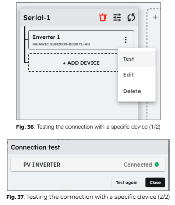
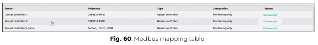
When you run a connection test from eConf interface, the ePowerLog sends a read request to the connected equipment.
● If the test is successful, the device status will be displayed as “Connected”.
● If the test fails, the device status will be shown as “Disconnected”.
ℹ️️ Driver error
If the test returns a “Driver error”, it means the device is “Connected”, but the driver needs to be updated remotely by Elum. In this case, please notify the Elum Deployment Team for assistance.
6. Once all ports and devices have been correctly configured and all connection tests have been successful, click “Continue” to proceed.
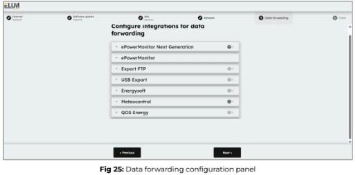
Configuring data forwarding (optional)
Elum offers an optional data export feature, allowing data to be forwarded to third-party platforms or USB devices. If you do not need to export data to any platform other than ePowerMonitor or to a USB device, click “Skip” to move to the next configuration section.
Available Data Export options:
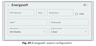
- FTP Push to Energysoft: Exports data to the Energysoft monitoring platform using the S4E PowerAPI data format.
- FTP Push to Other Servers: Sends data to any internal or external server supporting the FTP protocol, using the Elum Energy data format.
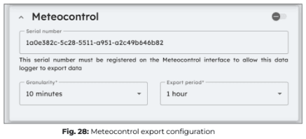
- Meteocontrol Export: Enables data export to the Meteocontrol platform. The serial number of the controller must be registered on the Meteocontrol interface for data export to be enabled. Users can configure:
- USB Export: Saves data directly to a USB device for local storage.
ℹ️️ For more details about the Elum Data Export feature and supported data formats, contact Elum support at support@elum-energy.com.
ℹ️️ If needed, all export methods can be activated simultaneously.
Start by selecting an export method from the available options. Once chosen, you will be prompted to enter additional details required to configure the data forwarding settings.
Export FTP
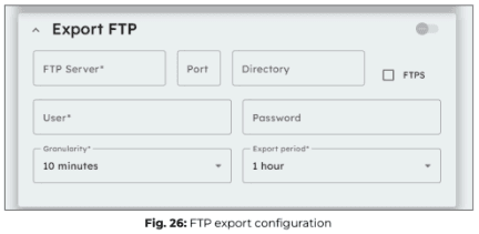
- Enter the FTP server details, including the server address, port, and directory, where you want to forward your data.
- Provide your user credentials (Username and Password) to authenticate access to the specified FTP server.
- Set the data granularity, which determines how frequently data points are recorded before being forwarded. This can range from 5 minutes to 1 day.
- Specify the export period, which defines how often the collected data is sent to the FTP server. This setting is independent of granularity and can range from 10 minutes to 1 day.
- Enable FTPS (via the checkbox) if you require a secure connection using FTP over SSL/TLS to enhance data encryption and security during transmission.
Energysoft
The Energysoft export method operates using the FTP protocol, similar to Elum’s standard FTP push service, with the only difference being the export file format. Therefore, the same FTP forwarding settings apply to both methods.
For further information see previous section Export FTP.
Meteocontrol Export
The Meteocontrol export option enables the ePowerLog to forward data to the Meteocontrol platform for monitoring and analysis. To activate this feature, the serial number displayed on the eConf platform must be registered on the Meteocontrol interface.
Configuration parameters:
- Serial number: The unique identifier generated by eConf, which must be registered in the Meteocontrol platform to activate data export.
- Granularity: Defines how often data is collected before being forwarded. This can be set between 5 minutes and 1 hour.
- Export period: Determines how often the collected data is sent to Meteocontrol, with options ranging from 10 minutes to 1 day.
USB Export
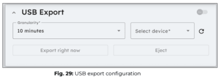
When a USB device is plugged into the Elum Explorer USB port, it will appear in the device selection list within the USB export configuration panel. Select the USB device where you want to forward your data.
Configuration parameters:
- Granularity: Defines how often data is collected before being saved to the USB device.
- Export Period: The export period is fixed at 24 hours, with all data being exported once per day at 00:00 UTC.
Manual data export & Ejecting USB device
- By clicking “Export right now”, the data from the current export period will be immediately saved to the USB device.
- It is highly recommended to use “Export right now” just before ejecting your USB device to ensure all collected data is saved.
- To safely remove your USB device, click “Eject” before physically unplugging it.
- Failure to eject the USB device properly may result in data loss or permanent damage to the USB storage.
ℹ️️ To prevent damage to your USB device and avoid irreversible data loss, always eject the USB device before physically removing it from the Elum Explorer USB port.
Starting the EMS
1. Confirm that you want to complete the setup by clicking on “Finish Setup”.
The data entered during the setup process can be modified later through eConf
platform.

2. Once you click on the “Finish Setup” button, you will be redirected to the
Overview page of eConf platform for ePowerLog.
7. eConf navigation after the commissioning
Accessing eConf
After deploying the ePowerLog, the eConf interface remains accessible at any time for further adjustments or diagnostics.
To access the interface:
1. Connect your laptop to LAN2 (for DL 500 and DL 1000) or LAN4 (for DL 3000 and DL 10000) of the Central Computing Unit (CCU).
2. Open a web browser and enter 192.168.4.127 in the URL bar.
User interface: eConf
General information
The main purposes of eConf are:
- To configure the site: Set up network parameters, connected devices, and system settings.
- To define the control rules: Establish operational rules for managing site behavior.
- To monitor the logs: Track system logs, events, setpoints, and errors.
- To monitor the behavior of the site: Observe real-time data and performance of all connected devices.
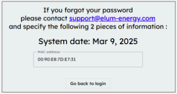
ℹ️️ Forgot password?
If the User password is forgotten, Elum can generate a backup password upon request.
This backup password will be valid for 24 hours and can be used to log in and set a new password from the Password panel in eConf interface.
Supported language
The eConf interface supports the following languages:
- English
- French
The language selection is automatically determined by the browser’s language settings.
In solutions that include a screen, it may not always be possible to change the browser’s language. If this issue occurs, please contact Elum Support for guidance and assistance.
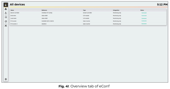
Overview
The Overview panel is the main interface for ePowerLog operators, providing
a real-time summary of the plant’s status. It includes:
- Power Monitoring: Shows the active and reactive power of each connected unit.
- Maintenance status: Displays the number of devices currently under maintenance.

You can navigate through eConf interface using the left-side menu, which provides access to different configuration and monitoring panels.
Available panels in the Left-Side Menu:
- Elum Logo: Clicking on the logo will return you to the homepage of the interface.
- “Network” panel: Used to configure LAN connections, serial connections for devices, and internet connectivity.
- “Data Forwarding” panel: Provides access to data export options, enabling configuration for exporting data to third-party platforms or USB storage.
- “All Devices” panel: Displays the status of all devices connected to the ePowerLog
and provides access to individual device data acquisition. - “Logs History” panel: Allows access to the history of logs, setpoints, and errors for system diagnostics and analysis.
- “System Settings” panel: Enables modification of various system settings and parameters, allowing customization of the ePowerLog configuration
A User can log out at any time by clicking on the logout button located in the
bottom left corner of the eConf.
![]()
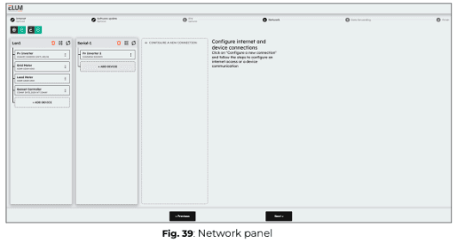
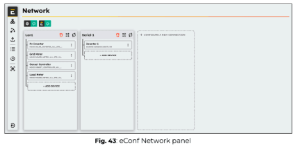
Network panel
The “Network” panel provides access to network settings, allowing users to configure and manage network interfaces. Within the network menu, users can:
- Create or configure network interfaces (Serial or LAN)
- Add devices to a configured interface
Data Forwarding
Data forwarding manages all specific data exchange methods between the EMS and third-party solutions that do not use the Modbus gateway for data transfer. The Data Forwarding panel allows you to modify the data forwarding settings that were initially configured during commissioning.
Available data forwarding interfaces
- ePowerMonitor
- ePowerMonitor Next Gen
- Export FTP
- Export USB
- Energysoft
- QOS Energy
- Meteocontrol
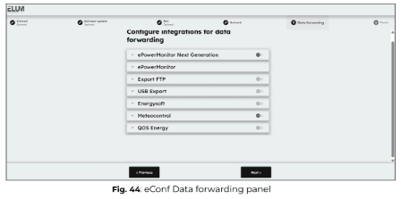
In eConf, the Data Forwarding page allows you to configure connections with different interfaces. All mandatory settings are displayed, and once they are completed, data forwarding can be activated. Some advanced parameters can be modified in a configuration file.
| Interface | Description |
| ePowerMonitor | Sends all data from the Elum Data Model to the Elum asset management platform: ePowerMonitor. Activated upon subscription to ePowerMonitor |
| FTP | Allows sending data from the EMS to an FTP server. All data from the Elum Data Model is transferred. |
| USB | Enables exporting data from the EMS to a local USB key. All data from the Elum Data Model is transferred. |
| Energysoft | Sends available data from the Elum Data Model to the Energysoft platform. |
| QOS Energy | Sends available data from the Elum Data Model to the QOS Energy platform. |
| Meteocontrol | Sends available data from the Elum Data Model to the Meteocontrol platform. |
Devices
The Devices panel displays a list of all equipment connected to the ePowerLog, along with their current connection status.

By selecting a device in the “All Devices” panel, you can view its detailed live data to monitor its real-time performance and status.
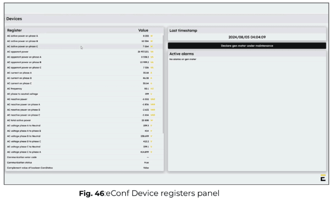
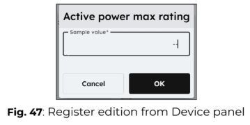
The live data panel displays all accessible read and write registers for the selected device. Some registers can be edited by clicking on the edit icon. When modifying a register, you will be prompted to enter a new value for the specific device and confirm your choice.

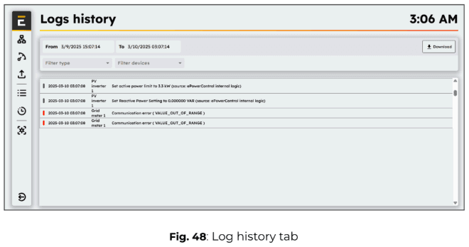
Logs
The Logs History panel provides access to timestamped logs of EMS events, enabling system diagnostics and analysis.
Available Log categories:
- Communication Errors: View a list of communication failures between devices.
- Device Errors: Check any device-related malfunctions detected by the system.
- Setpoints: Monitor the setpoints sent by the EMS to the plant for control operations.
Filtering and exporting Logs:
You can:
- Select a start and stop date to filter logs for a specific time range.
- Export the log data in CSV format for further analysis.
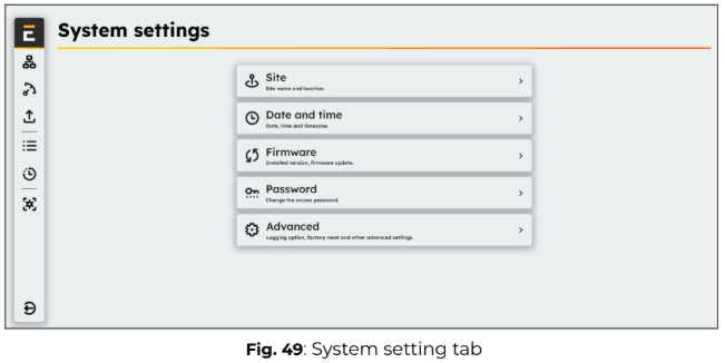
System settings
The System Settings panel allows you to access and configure essential system parameters.
Available settings:
1. Site: Enter the site name and its location details.
2. Date and Time: Define and adjust the date, time, and time zone settings.
3. Firmware: Check the installed firmware version and update if necessary.
4. Password: Change the login password for accessing eConf.
5. Advanced settings: Access additional system configurations, including logging options and factory reset.
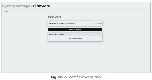
Version
The “Firmware” panel shows the version of the Elum firmware packages installed on your ePowerLog.
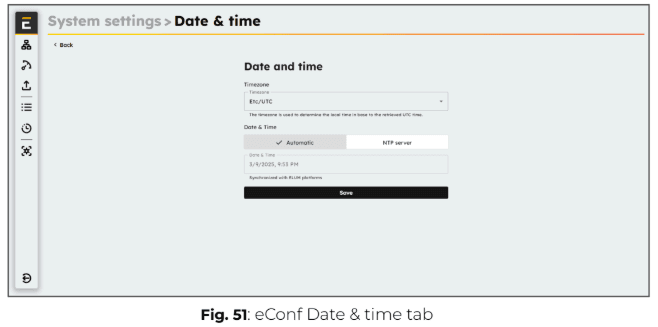
Date
The “System settings” panel allows you to access and configure the Date & Time settings, including the Timezone.
By default, if the Explorer is connected to the internet, it will automatically synchronize its clock with Elum platforms. Alternatively, it can be configured to sync with a custom NTP server.
In the absence of an internet connection, the date and time must be set manually via the interface.
Proper configuration of date and time is essential to ensure accurate timestamping of all monitored values.
ℹ️️ Timestamps are recorded in UTC, meaning the time zone setting does not affect them. The timestamp assigned to the data corresponds to the midpoint of the reading operation. For example, if the reading starts at 12:35:30 and takes 3 seconds to complete, all variables will be assigned the timestamp 12:35:31.5.
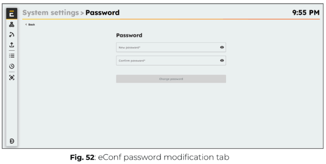
Password
The Password panel allows you to set a new password for accessing the system.
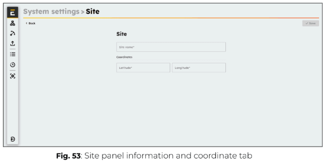
Site
The Site panel allows you to modify the site settings, with new settings overwriting the previous ones.
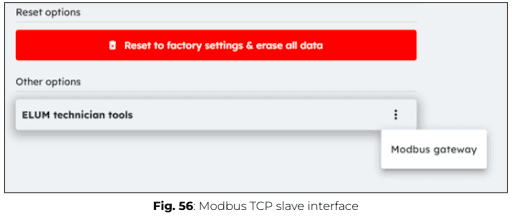
Advanced
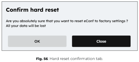
The Advanced panel allows an Advanced User to reset the ePowerLog configuration to factory settings.
⚠️ This action will permanently delete all personal data, and restoration will not be possible.
The Advanced panel also provides access to the Modbus Gateway interface of the Elum Controller. To access it, click on “Elum Technician Tools”, then select “Modbus Gateway”.
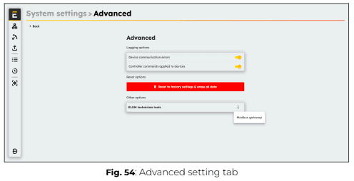
From this menu, you can select the LAN port of the Elum Explorer to be exposed for external Modbus masters to send queries. Additionally, you can configure the slave ID for each device connected to the Elum Explorer.
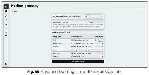
For more details about the Elum Modbus Gateway interface, please refer to Appendix D: Modbus Gateway.
ℹ️️ Please note that this option is only available when ordering your Elum Explorer. If you wish to subscribe to this additional feature after purchase, please contact the Elum sales team at sales@elum-energy.com.
Options and accessories
8.1. Cabinets


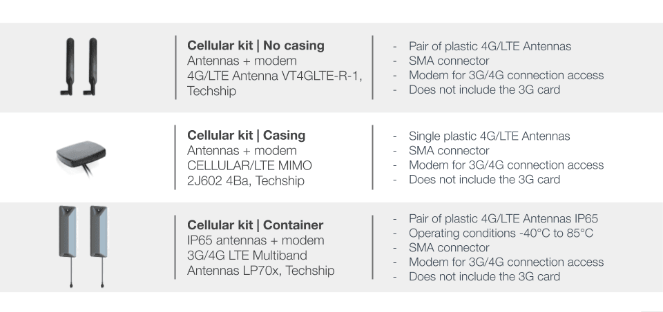
8.2. Antennas
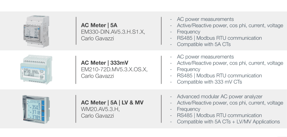
8.3. Meters
8.4. UPS
8.5. Connectivity
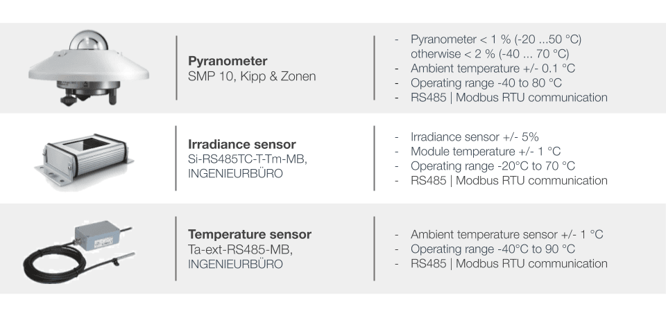
8.6. Weather Sensors

Appendix A : Modbus gateway
About the feature
The Modbus Gateway feature, also known as the Modbus TCP Slave Interface, is a standard feature available in all Elum ePowerLog and ePowerControl series products. Modbus TCP is an industry-standard protocol that allows SCADA systems and third-party equipment to interface with Elum products.
With the Modbus TCP interface, users can:
- Read standard data from devices connected to the Elum Explorer.
- Read and/or write custom data from the EMS to the ePowerControl PPCs.
This manual provides all the necessary information to configure and operate the Elum Explorer’s Modbus TCP Slave Interface.
The following symbol will help guide the reader through the document by highlighting important information:
ℹ️️ Notes
Notes provide background information for the reader to keep in mind while configuring and operating the system.
Glossary
| Modbus TCP | Gateway between a GSM, GPRS, 3G or 4G mobile network and another computer network |
| SCADA | Supervisory Control And Data Acquisition system |
| PPC | Power Plant Controller |
| IP address | Identification number of each device connected to a network |
| LAN | Local Area Network, a LAN is a group of connected computers or devices |
| EMS | Energy Management System (EMS) |
| RESEARCH AND DEVELOPMENT | Research and development |
| Explore | Generic term for the central unit of Elum’s monitoring and control solutions |
Configuration of the Modbus TCP slave interface of the ePowerControl PPC
Procedure
| Step 1 | Plan the communication architecture and connect the Modbus master | |
| Step 2 | LAN network settings | |
Path | Settings/Network/LAN/Edit | |
Parameters | – LAN port | |
| Step 3 | Activation of the slave interface | |
Path | Settings/Advanced/Other options/ELUM | |
Parameters | – LAN port | |
| Step 4 | Setting the slave interface | |
Path | Settings/Advanced/Other options/ELUM technician/…/Modbus Gateway | |
Parameters | – Gateway_id | |
LAN network settings
Configure the LAN port to which the Modbus master is connected by navigating to
Settings > Network > LAN > Edit. The network settings of the LAN port must be compatible with those of the Modbus master, as the IP address assigned to the LAN port will be used to address Modbus requests.
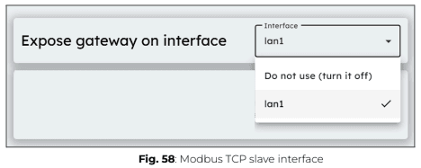
Activation of the slave interface
By default, the Modbus TCP Slave Interface is disabled. To enable it, navigate to Settings > Advanced > Other Options > ELUM Technician > … > Modbus Gateway.
Then, select the Explorer LAN port to be used for the Modbus TCP Slave Interface. Choose the Explorer LAN port that is connected to the Modbus master to ensure proper communication.
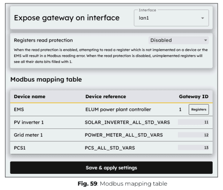
Setting the slave interface
The Modbus TCP protocol requires specific parameters for addressing requests:
- IP Address: This is the IP address of the LAN port where the Explorer 538/538i’s Modbus TCP Slave Interface has been activated. You can view and edit this address from Settings > Network > LAN > Edit.
- Port: The Modbus TCP communication port is always 502.
- Gateway ID: Also referred to as unit_id or slave_id in some SCADA software, this identifier is used to specify which device the Elum Explorer should read from or write to. The list of devices and their assigned slave IDs can be viewed and edited from Settings > Advanced > Other Options > ELUM Technician > … > Modbus Gateway.
ℹ️️ The slave_id of each device can be configured within the range of 11 to 254.
ℹ️️ For ePowerControl PPC Explorers, the slave_id is also used to select the EMS and its possible control sub-blocks, which are defined by the Elum R&D team. Slave IDs 1 to 10 are reserved for this purpose.
ℹ️️ In Modbus TCP, the slave_id does not have a predefined function, so application developers can use it as needed. The internal addressing system is freely configurable in this section.
It is important to note that the slave_id assigned here will likely differ from the slave ID used to identify devices in the Settings/Network menu.
Modbus addressing table
Accessible data according to Elum’s product
| Elum product | Accessible data | Access level |
| ePowerLog | – Standard data table | Read only |
| ePowerControl ZE/SD/HFS/MC | – Standard data table | Read only |
| ePowerControl PPC | – Standard data table | Read only |
| – Customized data table PPC | Read and/ or write according to specifications |
Read access to standard data
A SCADA system or any third-party device connected to the Modbus TCP Slave Interface of an Elum Explorer can read all standard data from devices linked to the Elum Explorer, using their assigned slave_id for identification.
ℹ️️ Device data is read-only.
A standard addressing table is defined for each device type based on the Elum Data Model. These standard addressing tables specify how data is structured and
accessed for different types of devices. The device type can be viewed in the Devices menu within eConf.
ℹ️️ Two devices of the same type will share the same addressing table, but they will always have different slave IDs.
ℹ️️ All registers in the standard address table will be available for each device, provided that the corresponding registers actually exist on the specific device being read. The available data may vary between different manufacturers, depending on the device’s supported registers.
Read and/or write access to EMS custom data (on ePowerControl PPC only)
A SCADA system or any third-party equipment connected to the Modbus TCP Slave Interface of an Elum ePowerControl PPC can read and/or write to the custom EMS data defined by Elum’s R&D team.
The EMS Addressing Table (Appendix C – Addressing Table) was provided to the client at the end of the design and development phase of the project.
This EMS addressing table can also be accessed directly from eConf by navigating to: Parameters > Advanced > Other Options > ELUM Technician > … > Modbus Gateway, then clicking on Registers in the line associated with the EMS.
ℹ️️ EMS data can have different access levels: read-only, read-write, or write-only. The Register Access parameter defines the level of access for each register.
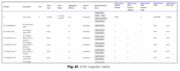
Parameters
Each register is defined by the following parameters:
- Register number: Specifies the address of the register.
- Function code: Defines the Modbus function code used for register access.
- Size: Indicates whether the register should be read in one or two words.
- Data type: Specifies the type of data according to Modbus standards.
ℹ️️ The data is already scaled, so no additional scaling factor is require.
Error codes and troubleshooting
Common errors
The most common cause of error is an incorrect association between the gateway_id and the register definition.
To verify and correct this:
- Check the gateway_id definition in Settings > Advanced > Other Options > ELUM Technician > … > Modbus Gateway.
- Refer to the Elum documentation for the correct register definitions.
Error codes
- Gateway path unavailable
If the Modbus master sends a request using a gateway_id that is not assigned to a device or the EMS, it will receive Modbus error code 10 (Gateway path unavailable). - Illegal function
If the Modbus master sends a request to the EMS using an unsupported function code (other than 1 (Read Coils), 3 (Read Holding Registers), 5 (Write Single Coil), 15 (Write Multiple Coils), or 16 (Write Multiple Registers)), it will receive Modbus error 1 (Illegal function). If the Modbus master sends a request to a device using an unsupported function code (other than 1 (Read Coils) or 3 (Read Holding Registers)), it will receive Modbus error 1 (Illegal function). - Illegal data address
If the Modbus master sends a request to an assigned gateway_id (EMS or device) with a valid function code, but the address does not map to any data, it will receive Modbus error code 2 (Illegal data address). - Device slave failure
If the Modbus master sends a request to an assigned gateway_id (EMS or device) using a valid function code and a mapped address, but the data is invalid for some reason, it will receive Modbus error code 4 (Device slave failure).