

Installation steps
● Wiring to Elum explorer
● Setting RS485 parameters
Wiring to Elum Explorer
The RS485 location and description is shown in the following figure:
| PIN | Pin signal |
| 37 | A |
| 36 | B |
| 35 | C |

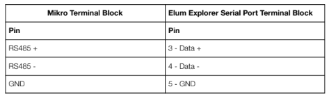
Connect the meter to Elum Explorer as shown in the following table:
| Elum Explorer Serial Port Terminal Block | A4x MeterTerminal block |
| Pin | Pin |
| 3 | B |
| 4 | A |
| 5 | C |
Setting RS485 parameters
To set the RS-485 communication using the local display, perform the following steps:

The procedure for accessing modbus communication parameters is the following:
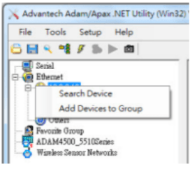
- Connect the module to your computer
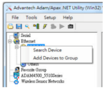
Select the Ethernet category on the Module Tree Display Area and click the Search Modules icon
The procedure for accessing modbus communication parameters is the following:
- Connect the module to your computer
- Select the Ethernet category on the Module Tree Display Area and click the Search Modules icon
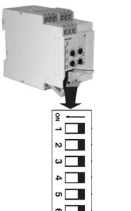
ℹ️ Switch 1: Input current range (terminals I1, I2 or 10, 11)
ON: 10A
OFF: 5A/MI
Switch 2: Relay status
ON: Relay de-energized in normal condition
OFF: Relay energized in normal condition
Switch 3: Working mode
ON: Contact input for start/stop functions
OFF: Contact input for latch/inhibit functions
Switch 4: Working mode
ON: Contact input for start/stop functions
OFF: Contact input for latch/inhibit functions
Switch 5 and 6: Measuring range

Wire the DWB03
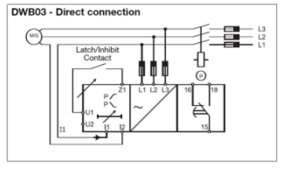
Wire the DWB03 according to the following wiring diagram: 
Point of connection n°15 should be connected to a power source and point of connection n°18 to the PV switch (or genset switch if not possible). So that when the relay detects a reverse power, point of connection n°15 is short-circuited with n°18 giving voltage to the main switch which opens and disconnects PV (or genset if not possible).
Wire the CT in reverse position
Wire the CT in reverse position, so that the current is measured as negative when supplied by the gensets.
Test the DWB03 integration
Turn on the genset, the genset must be automatically disconnected. If not, please review your wiring and configuration. If the test is successful, your DWB03 protection relay has been correctly wired and configured.
Wire the CT in the correct position
Wire the CT in the correct position so that the current is measured as positive when supplied by the gensets.
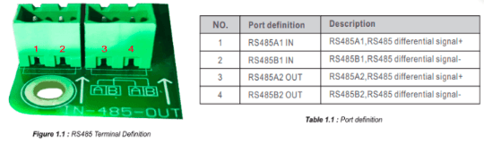
The RS485 port specifications are shown in the following table:


Wiring to Elum Explorer
The wiring of M C 485232 to Elum Explorer should be done as shown:
| Elum Explorer Serial Port Terminal Block | M C 485232 Terminal block |
| Pin | Pin |
| 3 | 1 |
| 4 | 2 |
| 5 | 4 |

Installation steps
- Wiring to Elum Explorer
- Setting modbus parameters
Wiring to Elum Explorer
The RS485 location and description are shown in the following figure:
| Pin number | Pin signal |
| 7 | Termination |
| 8 | B+ |
| 9 | A- |
| 10 | GND |

Connect the meter to Elum Explorer as shown in the following table:
| Elum Explorer Serial Port Terminal Block | EM340 Terminal block |
| Pin | Pin |
| 3 | 8 |
| 4 | 9 |
| 5 | 10 |
Additional instruments with RS485 are connected in parallel. The serial output must only be terminated if the meter is the last network device. The termination is done by connecting terminals A- and T as shown in the following figure:

Setting modbus parameters
Navigate through the meters pages using the buttons under the front display as shown here:

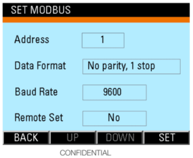
Set modbus parameters as follows:
- Address: Unique in the RS485 serial network (can be set from 1 to 247)
- BaudRate: 9600 baud
- Parity: None
- STOP bit: 1
Overview
ComAp InteliLite-NT AMF 20/25 is an AMF controller for single-generating sets operating in standby mode. IL-NT AMF25 features extended support for electronic engines and extension modules. InteliLite AMF 20/25 controllers communicate with Elum Explorer over Modbus RTU via a dedicated communication plug-in module.
Installation steps
- Plugging-in CM-RS232-485 Modbus communication module
- Configuration of CM-RS232-485 Modbus communication module
- CM-RS232-485 Firmware upgrade
- Wiring the inverters to Elum Explorer
Plugging-in CM-RS232-485 Modbus communication module
CM-RS232-485 is an optional plug-in card to enable InteliLite
the RS232 and RS485 communication. This is required for a computer or MODBUS connection. The CM-RS232-485 is a dual port module with RS232 and RS485 interfaces at independent COM channels. The RS232 is connected to COM1 and RS485 to COM2.

The RS485 internal wiring is as follows:

The module is plugged into the slot located on the rear side of the controller, the procedure is the following:
- Remove the back cover. To do this, press four holders which are located in the corners.
- Insert the plug-in module under holders marked by symbol 1. Then insert the plug-in
module undernholders marked by symbol 2. - After locking the plug-in module into holders, place back the back cover.
- Finally insert the small cover for the connectors. Small covers are unique for each plug-in
module.

Overview
The DSE7310 is an Auto Start Control Module and the DSE7320 is an Auto Mains (Utility) Failure Control Module suitable for a wide variety of single, diesel or gas, gen-set applications.
The communication protocol embedded is Modbus RTU using half duplex 2 wires connection.
Installation steps
- RS485 | Modbus RTU
- Communication wiring
- Modbus setting
Modbus RTU:
Communication wiring:
DSE7300 RS485 pinout:

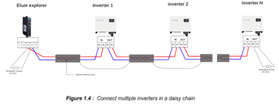
Connect multiple genset controllers in the Daisy Chain:
When connecting multiple genset controllers, the following procedure should be followed:
- Connect the RS485 differential positive and negative signal of the explorer to terminal RS485 B and RS485 A of the first equipment.
- Connect terminal RS485 A and RS485 B of the first inverter in the daisy chain, to terminal RS485 A and RS485 B of other equipment.
- Repeat step 2 for all equipment on the same daisy chain.
- Terminate the daisy chain on both ends using 120 ohms termination resistors.

To set the Modbus RTU parameters we have either to use the DSE HMI or use the DSE Configuration Suite PC Software.
❖ Access to the DSE Configuration Suite Software
❖ Navigate to the Serial Port Configuration menu
❖ Configure the Slave ID, Baud Rate and Port Usage according to your Communication Architecture Plan.

Overview
DSE 8610 MKII modules can operate as a Modbus RTU slave device. The factory settings are for the module to communicate at 115200 baud, Modbus slave address 10. DSE 8610 MKII modules can also operate as a Modbus TCP slave device.
If you want to change those parameters according to your Communication Architecture Plan you can do it from the DSE Configuration Suite Software.
Installation steps
- Configure the Deepsea DSE 8610 MKII
- Connect the Deepsea DSE 8610 MKII to Elum Explorer
Configure the Deepsea DSE 8610 MKII
- RS485 | Modbus RTU:
- Access to the DSE Configuration Suite Software
- Navigate to the Serial Port Configuration menu
- Configure the Slave ID, Baud Rate and Port Usage according to your Communication Architecture Plan

ℹ️ ‘Master inactivity timeout’ should be set to at least twice the value of the longest “Response timeout” you set up on any device from Elum Configuration. If “Response timeout” remained by default on Elum Configuration, set it to 10s.
ℹ️ RS485 | Modbus RTU diagnostic screens are included; press the Scroll Down 

- Ethernet | Modbus TCP:
- Access to the DSE Configuration Suite Software
- Whilst in the Communication section, press the Scroll Down

- Configure the IP Address, Subnet mask and TCP port according to your Communication Architecture Plan
- Reboot the DSE 8610 MKII module
Connect the Deepsea DSE 8610 MKII to Elum Explorer
- RS485 | Modbus RTU: Connect the RS485 port of the genset controller to the Serial Port 1 or 2 of the Elum Explorer.
- Ethernet | Modbus TCP: Connect the Ethernet port of the genset controller to the LAN 1 Ethernet port of the Elum Explorer.
Overview
The DSE74xx MKII is an Auto Mains (Utility) Failure Control Module suitable for paralleling single gensets (diesel or gas) with the mains (utility) supply. Designed to synchronize a single genset with a single mains (utility) supply, the DSE86xx will automatically control the changeover from mains (utility) to generator supply or run the generator in synchronization with the mains (utility) to provide no-break, peak lopping and peak shaving power solutions.
Installation steps
- RS485 | Modbus RTU
- Communication wiring
- Modbus setting
- Ethernet | Modbus TCP
Modbus RTU:
Communication wiring:
DSE74xx MKII RS485 pinout:

Connect multiple genset controllers in the Daisy Chain:
When connecting multiple genset controllers, the following procedure should be followed:
- Connect the RS485 differential positive and negative signal of the explorer to terminal RS485 B and RS485 A of the first equipment.
- Connect terminal RS485 A and RS485 B of the first inverter in the daisy chain, to terminal RS485 A and RS485 B of other equipment.
- Repeat step 2 for all equipment on the same daisy chain.
- Terminate the daisy chain on both ends using 120 ohms termination resistors.

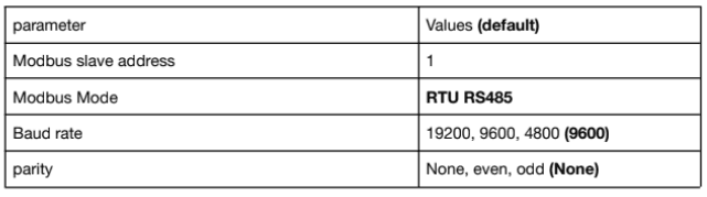
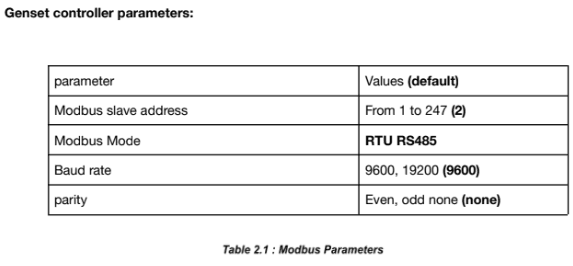
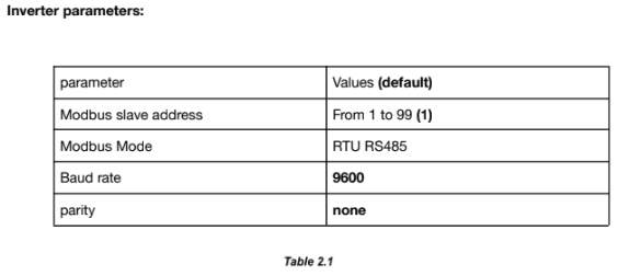
Genset controller parameters:
| parameter | Values (default) |
| Modbus slave address | From 10 to 247(10) |
| Modbus Mode | RTU RS485 |
| Baud rate | 4800, 9600 19200 (115200) |
| parity | Even, odd none (none) |
To set the Modbus RTU parameters we have either to use the DSE HMI or use the DSE Configuration Suite PC Software.
❖ Access to the DSE Configuration Suite Software
❖ Navigate to the Serial Port Configuration menu
❖ Configure the Slave ID, Baud Rate and Port Usage according to your Communication Architecture Plan.

Modbus TCP:
– Ethernet connection:

ℹ️ A crossover Ethernet cable (two pairs crossed, two pairs uncrossed) is required to establish a direct connection between the DSE8620 and the Elum controller.

– Modbus TCP setting:
Whilst in the ‘ABOUT’ section, press the Scroll Down

Press the Scroll Down

Overview
The DSE86xx is an Auto Mains (Utility) Failure Control Module suitable for paralleling single gensets (diesel or gas) with the mains (utility) supply. Designed to synchronize a single genset with a single mains (utility) supply, the DSE86xx will automatically control the changeover from mains (utility) to generator supply or run the generator in synchronization with the mains (utility) to provide no-break, peak lopping and peak shaving power solutions. The communication protocol embedded is Modbus RTU using half duplex 2 wires connection.
Installation steps
● RS485 | Modbus RTU
- Communication wiring
- Modbus setting
● Ethernet | Modbus TCP
Modbus RTU:
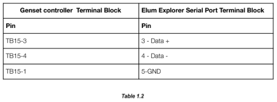
Communication wiring:
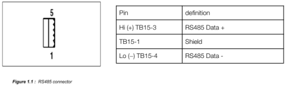
DSE86xx RS485 pinout:

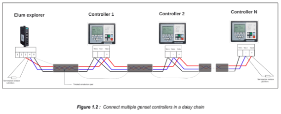
Connect multiple genset controllers in the Daisy Chain:
When connecting multiple genset controllers, the following procedure should be followed:
- Connect the RS485 differential positive and negative signal of the explorer to terminal RS485 B and RS485 A of the first equipment.
- Connect terminal RS485 A and RS485 B of the first inverter in the daisy chain, to terminal RS485 A and RS485 B of other equipment.
- Repeat step 2 for all equipment on the same daisy chain.
- Terminate the daisy chain on both ends using 120 ohms termination resistors.
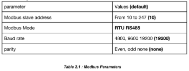
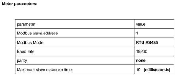
Genset controller parameters:
| parameter | Values (default) |
| Modbus slave address | From 10 to 247(1) |
| Modbus Mode | RTU RS485 |
| Baud rate | 4800, 9600 19200 (19200) |
| parity | Even, odd none (none) |
Table 2.1 : Modbus parameters
Modbus TCP:
– Ethernet connection:
ℹ️ A crossover Ethernet cable (two pairs crossed, two pairs uncrossed) is required to establish a direct connection between the DSE8620 and the Elum controller.
Modbus TCP setting :
Whilst in the ‘ABOUT’ section, press the Scroll Down button to access more information about the network settings.
Network settings can be configured using DSE Configuration Suite Software. The module must be rebooted for the changes to take effect.
Press the Scroll Down
Overview
Delta RPI MxA is a series of 3-phase solar inverters for commercial applications. All delta RPI MxA inverters can communicate with Elum Explorer using Sunspec modbus protocol communication protocol via their RS485 interface. The communication procedures in this section are only dedicated to the following models:
- Delta RPI M15A
- Delta RPI M20A
- Delta RPI M30A
- Delta RPI M50A
Installation steps
- Identification of communication pins
- Wiring to Elum Explorer
- Setting modbus slave address
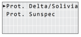
- Setting the communication protocol to Sunspec
Identification of communication pins
The connections for RS485, the dry contacts and the external power off (EPO) are all located on the communications card. These installation tasks can therefore be combined. The communication card components are shown below:

The RS485 connector is used to connect the inverters of the PV plant to a monitoring system. For connecting RS485, Pins 3 to 6 are used. For connecting RS485, terminals 3/4 or 5/6 are used. It does not matter which pair of terminals you use. The second pair is only when connecting multiple inverters via RS485.

4. If no further inverter is connected, terminate the inverter
5. Close the inverter if no other inverters are to be connected.
6. Insert the terminal block connector into serial port 1 of Elum Explorer.
The RS485 connections on the terminal strip are each double connections so that the wiring can be continued to the next inverter.
When connecting Multiple multiple inverters, the following procedure should be followed:
- Connect the data cable in the free terminals of the first inverter – 2 (GND), 3 (Data+) and 4 (Data-).
- Connect the other end of the data cable in the free terminals of the second inverter – 2
(GND), 5 (Data+) and 6 (Data-). - Connect the other inverters to each other in the same way.
- Terminate the last inverter: Set the switch inside the inverter to ON and all other inverters to OFF.

Overview
Delta RPI-H3 and Delta RPI-H5 inverters are single-phase grid-tie solar inverters, they can communicate with Elum Explorer over soliavia communication protocol using an integrated RS485 communication module
Installation steps
- Plug in the RS485 communication module
- Set the inverter’s ID
- Wire to Elum Explorer
Taking off the RS485 communication module
The Communication Module enables the inverter to communicate with Elum Explorer and provides 2 ports of RS-485.
When using this module, the first step is to take off the cover located at the right bottom of the inverter and pull out the RS485 socket as shown in the following Figure.

Setting the inverter’s ID
Multiple devices could be monitored via RS-485 daisy chain connection, but each device needs to have a unique communication ID.
- Turn on DC power and wait for the LCD display to be ok
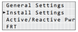
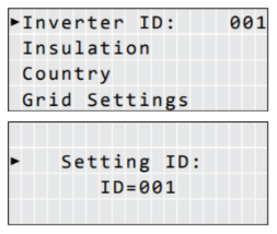
- Press the “Select” button until “Inverter ID: XX” is shown in LCD
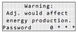
- Press and hold both buttons (“Enter” first then “Select”) until entering the setting ID screen
- Release both buttons and set the ID by pressing the “Select” button, and press “Enter” button if the ID is correct (ID = 1 ~ 254)
The inverter ID setting is illustrated in the following figure:

Overview
The SC 200 system controller is an advanced control and monitoring device. The system can communicate with Elum Explorer using TCP modbus protocol communication protocol via Ethernet interface.
Installation steps
- Device Schema
- Wire to Elum Explorer
- Setting and enabling the Modbus TCP protocol
Device Scheme

Overview
eGauge EG4xxx is used by Elum Energy as a power meter that can measure up to five 3-phases circuits. It can measure and record the total building electrical consumption of individual circuits, these circuits are referred to by Elum as metering points. eGauge devicescommunicate with Elum Explorer over Modbus TCP communication protocol via an Ethernet-RJ45 interface.

Installation steps
- Accessing the eGauge
- Setting Modbus Server parameters
- Configuring a Static IP Address
- Wiring to Elum Explorer
Accessing your eGauge
Connect the Ethernet port at the right side of the eGauge to your computer.

Once connected to the computer, you can access your eGauge with a web browser. To start, enter the following Web address into your web browser:
- Microsoft Windows: http://devname/
- All other computers: http://devname.local/
Where devname is the name of the device (e.g., eGauge9999). For example, to access device
eGauge9999, you would enter the following URL into your browser:
- Microsoft Windows: http://egauge9999/
- All other computers: http://egauge9999.local/
You may also use the LCD display to find the local IP address of the eGauge on the network. Use the multi-switch on the main register display to scroll to the last page containing the hostname and IP address of the eGauge. the device will default to using IP address 192.168.1.88, so the device can be accessed as: http://192.168.1.88/.
Setting Modbus Server parameters
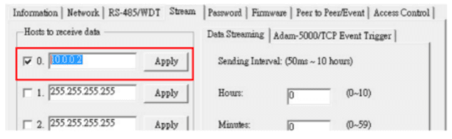
Once the device page is working, the modbus parameters should be configured as follows:
1. Navigate to Settings Settings→Modbus Server, the following settings will show up:

2. Set the unit ID to a unique value in your communication network
3. Enable Modbus TCP server
4. Set the TCP port to 502
5. Save the parameters
Setting static IP address
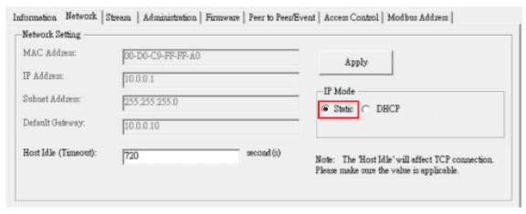
The eGauge normally automatically obtains its IP address and associated information through a service called Dynamic Host Configuration Protocol (DHCP). If another device ends up using the same address, or a static IP address is required. The IP address can be set as follows:
1. Navigate to Settings→Network Settings. The following page should show up:

Overview
The Fronius Datamanager is the communications center for Fronius inverters in every type of application. Elum Explorer communicates with Fronius inverters through the Datamanager over Ethernet | Modbus TCP.
Installation steps
● Configuration
● Wiring to Elum Explorer
Configuration
1. Connect your computer to the Fronius Datamanager using an ethernet cable
2. Switch the white “IP” jumper on the Fronius DataManager to position A :

Overview
The DT series GoodWe inverters can operate as a Modbus RTU slave device by connecting it through the serial port on the Elum Explorer. You will have to assign the addresses by configuring it through the LCD Screen as shown in this description.
Installation steps
- Configuration
- Wiring to Elum Explorer
- Setup on Elum Configuration
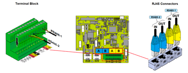
Wiring via 2-pin cable with terminal strip plug 
Wiring to Elum Explorer
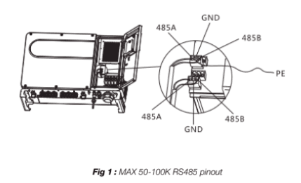
- Connect wires as shown in the diagram:
Elum Explorer Serial Port Terminal Block X4 socket RS485-1 inverter Terminal Terminal 3 1. RS485 + 4 2. RS485 – - Pass the cable from Elum Explorer to inverter 1 through the cable gland on the underside of the device and connect it to the RS485-Out terminal strip
- Plug the terminal strip plug into the RS485 serial port (1 or 2, depending on which one is available).
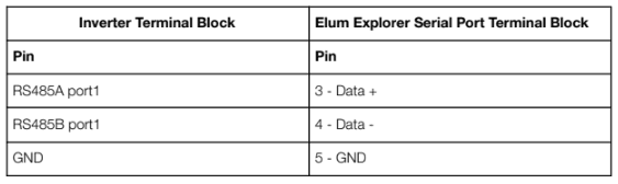
Connecting the inverters to each other
- Connect the inverter n° 1 via the RS485 terminal strip according to the manufacturer’s instructions.
- Connect the inverter n° 2 via the RS485 terminal strip from the inverter n° 1 according to the manufacturer’s instructions.
- Connect the other inverters to each other in the same way.
- Insert the terminal block connector into the RS485 serial port (1 or 2, depending on which one is available).
- Connect the last inverter according to the inverter instructions below.

Configuration on the Inverters end
To assign the addresses, use the LCD screen to navigate through the menus as shown below.

Overview
The MT series GoodWe inverters can operate as a Modbus RTU slave device by connecting it
through the serial port on the Elum Explorer. You will have to assign the addresses by configuring it through the LCD Screen as shown in this description.
Installation steps:
- Configuration
- Wiring to Elum Explorer
- Setup on Elum Configuration
Wiring via 3-pin cable with terminal strip plug 
Wiring to Elum Explorer
- Connect wires as shown in the diagram:
Elum Explorer Serial Port Terminal Block X4 socket RS485-1 inverter Terminal Terminal 3 1. 485_TX + 4 2. 485_TX – 5 3. PE (Earth) Or 3 5. 485_TX + 4 6. 485_TX – 5 4. PE (Earth) - Pass the cable from Elum Explorer to inverter 1 through the cable gland on the underside of the device and connect it with the terminal strip plug.
- Plug the terminal strip plug into the RS485 terminal strip of the inverter.
- Plug the terminal strip plug into the RS485 serial port (1 or 2, depending on which one is available).
Connecting the inverters to each other
- Connect the terminal strip plug into the RS485 socket of the inverter n°1.
- Continue wiring via RS485 socket to inverter 2 (according to manufacturer’s instruction).
- Connect the other terminal strip plug into the RS 485 socket of inverter n°2.
- Connect the other inverters to each other in the same way.
- Insert the terminal block connector into the RS485 serial port (1 or 2, depending on which one is available) as shown in « Figure 1 » and « Table 2 ».
- Connect the last inverter according to the inverter instructions.

Overview
The SmartLogger is an integrated device dedicated to monitoring and managing the PV power system. It converges ports, converts protocols, collects and stores data, and centrally monitors and maintains devices in the PV power system. The Smartlogger allows Modbus TCP communication with Elum Explorer. The Smartlogger allows RS485 or PLC communication with Huawei inverters.
An Elum controller connected to the Smartlogger can monitor and control all the inverters connected to this Smartlogger. All the PV inverters will then be monitored and controlled as one single system.

Installation steps
- Configure the Smartlogger to allow communication with Huawei Inverters
- Connect the Smartlogger to the Huawei inverters
- Configure the Smartlogger to allow Modbus TCP communication with Elum Explorer
- Connect the Smartlogger to Elum Explorer
- Allow remote power control on inverters
- Configure the Smartlogger device on Elum Configuration
Configure the Smartlogger to allow communication with Huawei Inverters
Please refer to Huawei instructions.
Connect the Smartlogger to the Huawei inverters
Please refer to Huawei instructions.
Allow remote power control on inverters
- Log in to the inverter SUN2000 App
- Go to Running Parameters -> Power Adjustment -> Remote Power Schedule
- Enable Remote Power Schedule
Configure the Smartlogger to allow Modbus TCP communication with Elum Explorer
- Log in to the SmartLogger WebUI.
Enter https://XX.XX.XX.XX (XX.XX.XX.XX is the IP address of the SmartLogger) in the
address box of the browser, and press Enter. The login page is displayed. You must log in as an Advanced User or Special User.

2. Navigate to the Comm. Param. / Settings / Modbus TCP / Settings menu

3. Activate Modbus TCP communicating by configuring the Link setting to: Enable
(Unlimited)

2. Start SiModbusConfigurator0.n

3. Select the COM port the sensor is connected to, and press “Open Port”. If the port is opened successfully, the green LED “Port opened” lights on. If the LED stays off make sure that the port exists and no other application does access to the selected port.

The SiModbusConfigurator0.n tries automatically to connect to the sensor. Therefore the Si-RS485 has to be in configuration mode. As the sensor stays in configuration mode for 4 seconds after power is on you may have to reset the sensor to establish the connection (switch the power supply of the sensor off and on). If the connection is established the green LED “Sensor connected” lights on and the actual MODBUS parameter is read from the Si-RS485.

To change the MODBUS parameter (MODBUS address, baud rate and data format) select the required setting in “MODBUS Parameter” and press “Set Parameter”.
4. Set the RS485 | Modbus RTU communication parameters according to your Communication Architecture Plan

If needed, you can change to MODBUS communication by pressing “Switch to MODBUS mode”. Si Modbus Configurator 0.n re-opens the COM port with the actual bus parameter of the Si-RS485 and Changes to MODBUS communication.

Overview
The TL M Series of the INGECON SUN 1Play inverters is a series of solar string inverters ranging from 2.6 to 6KW. It is possible for the Ingeteam inverters to communicate with Elum Explorer over the Modbus RTU protocol via an optional RS485 interface.
In order to connect the inverter to Elum Explorer via RS485, one of the following accessories is needed:
| Code | Description |
| AAX7051 | RS-485 kit for horizontal assembly |
| AAX7052 | RS-485 kit for vertical assembly |
Supported models:
- INGECON® SUN 1Play 2.5TL M
- INGECON® SUN 1Play 3TL M
- INGECON® SUN 1Play 3.3TL M
- INGECON® SUN 1Play 3.68TL M
- INGECON® SUN 1Play 4.6TL M
- INGECON® SUN 1Play 5TL M
- INGECON® SUN 1Play 6TL M
Installation steps
- Installing the RS485 interface in the inverter
- Wiring to Elum Explorer
- Allocating the communication address
Installing the RS485 interface in the inverter
Install the RS485 interface in the inverter in accordance with the interface card installation
instructions sheet.
Wiring to Elum Explorer
The communication cards are wired to the RS485 network as follows:

Allocating the communication address
The Modbus ID is the inverter’s identification number within the communications bus. In order to access and edit the modbus address, navigate through the main menu as shown below:

Set the communication address COMM 2 to a unique value in your RS485 network.
Overview
The Kaco powador series are three-phase string inverters for photovoltaic systems for both commercial and utility applications. The Powador series inverters communicate with Elum Explorer over Modbus TCP communication protocol via an RJ45 physical interface.
Installation steps
● Wiring to Elum Explorer
● Enable TCP Modbus communication
Wiring to Elum Explorer
An RJ45 wire is needed to connect both ends.
Connect the LAN ethernet wire on the LAN 1 port (or on the switch) of the Elum Explorer to the Ethernet port on the inverter housing door as shown in the following image.

Enable TCP Modbus Communication
In order to activate the Modbus TCP communication protocol, you will need to navigate through the LCD screen as shown:


How to change the IP address of the device and enable DHCP :

Overview
The Kehua France BCS-A series energy-storage converter is designed to convert energy between
storage systems and the electricity distribution grid in both directions. The BCS-A can communicate with Elum Devices over Modbus RTU using one of the device’s RS485 communication interfaces.
Installation steps
● Wiring to Elum Explorer
● Accessing the device as an administrator
● Setting communication parameters
Wiring to Elum Explorer
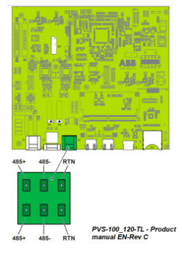
The RS485 communication interface used to interface with Elum Explorer is located at the external wiring terminal bar of the energy-storage converter as shown in the following figure.

Pins 11 and 12 are used for communication as mapped in the table below.
| Pin number | Pin signal |
| 11 | RS485 A or D- |
| 12 | RS485 B or D+ |
The BCS should be wired to Elum Explorer with reference to the following table:
| Elum Explorer Serial Port Terminal Block | External wiring terminal block |
| Pin | Pin |
| 3 | 12 |
| 4 | 11 |
Accessing the Device as an Administrator
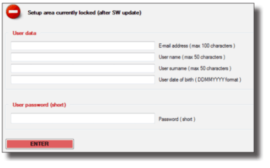
A login as an Administrator might be required to change the device settings. Logging into the device can be done as follows:
– On the main page, press the icon ![]()

– Enter the password and Press ENT, then click the Login icon.
Setting communication parameter
The device communication identifier and baud rate can be set using the device’s Touch Screen. The path to access the communication parameters is marked in the following diagram:

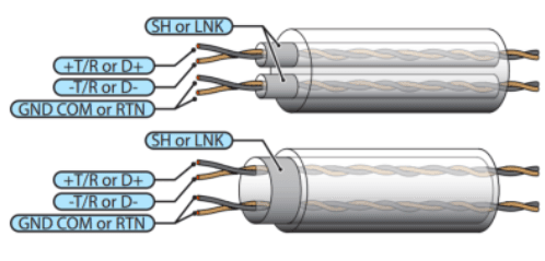
Identification of the communication wires
The communication pins are located on the output cable as shown in the picture below:


The Slaves may be an SMP Pyranometer or other devices but the master, the last device on the RS485 network must be the Elum Explorer. The LT (line terminator) consisting of a 120 Ω or 150 Ω resistor, must be connected between terminals A/A’/- and B/B’/+.
Overview
The MGate MB3170 and MB3270 are 1 and 2-port advanced Modbus gateways that convert between Modbus TCP and Modbus ASCII/RTU protocols. They can be used to allow Ethernet masters to control serial slaves, or to allow serial masters to control Ethernet slaves. Up to 32 TCP masters and slaves can be connected simultaneously. The MGate MB3170 and MB3270 can connect up to 31 or 62 Modbus RTU/ASCII slaves, respectively.
Installation steps
- Installing the MGate
- Configuring the MGate
- Connecting the MGate to the slaves
- Connecting the MGate to the master i.e. the Elum Explorer
- Configuring the Elum Explorer
Installing the MGate
The MGate MB3170/3270 is designed to be attached to a DIN rail or mounted on a wall. The two sliders on the MGate MB3170/3270 rear panel serve a dual purpose. For wall mounting, both sliders should be extended. For DIN-rail mounting, start with one slider pushed in, and the other slider extended. After attaching the MGate MB3170/3270 on the DIN rail, push the extended slider in to lock the device server to the rail. The two placement options are illustrated in the accompanying figures
Connect the 12 to 48 VDC power source to the terminal block power input, use Power Input 1 and Shielded Ground.

Login into the Moxa configuration platform using the default user credentials:
– Default account: admin
– Default password: moxa

Configure the Network settings according to your Communication Architecture Plan from the Network Settings menu.

Configure the RS485 settings of each port according to your Communication Architecture Plan from the Serial Settings menu.

Depending on your Communication Architecture Plan you might also need to add routing to each of the serial ports of the MGate, from the Serial Settings/Protocol Settings/Modbus Routing menu.
Save and restart the settings applied in the MGate from the Save/Restart menu, to do so, just click on Submit.

Connecting the MGate to the slaves
The MGate MB3170 has a male DB9 port and a terminal block for connecting to serial devices. The MGate MB3270 has two DB9 connectors for connecting to serial devices.
Connect the MGate to the different slaves to be monitored and/or controlled by the Elum Explorer according to your Communication Architecture Plan.

The Network Panel configures the LAN port connected to the MGate according to your
Communication Architecture Plan.
Add a device on this same LAN port connected to the MGate and configure it as described below:
– Reference: “Reference of your equipment via MGate”
– Protocol: MODBUS_TCP
– IP: IP of the MGate
– Port: Port associated used to connect the device to the MGate
– Slave_id: Slave ID of the device connected to the MGate

Overview
The Rover series charge controllers are suitable for various off-grid solar applications. This Battery management system can communicate with Elum Explorer over Modbus RTU via an RS232 physical interface.


Installation steps
● Wiring to Elum Explorer
Wiring to Elum Explorer
From the rover’s end:

| Rovers pin number | Description |
| 1 | DCD |
| 2 | Rx |
| 3 | Tx |
| 4 | DTR |
| 5 | GND |
| 6 | DSR |
| 7 | RTs |
| 8 | CTs |
| 9 | RI |
From the explorer’s end:

| Explorer Serial port pin number | Description |
| 1 | TxD |
| 2 | RxD |
| 3 | RTs |
| 4 | CTs |
| 5 | GND |
Wiring both ends:
| RS 232 Pin Number | Description | Elum Explorer serial port PIN |
| 3 | TxD | 1 |
| 2 | RxD | 2 |
| 7 | RTs | 3 |
| 8 | CTs | 4 |
| 9 | GND | 5 |
Overview
The PM5300 is a power meter provided for the measurement and calculation of electrical
parameters such as voltage, current, power, energy, etc. for building installations, to distributors, circuit breakers and busbar trunking systems. The communication protocol embedded is Modbus RTU using half duplex 2 wires connection.
Installation steps
- Wire communication
- Set Modbus
Communication wiring:
PM3500 RS485 pinout:

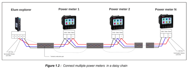
Connect multiple devices in a single Daisy Chain:
When connecting multiple equipments, the following procedure should be followed, as per the diagram (figure1.2):
- Connect the RS485 cable from the Elum unit terminal to the serial port of the first meter.
- Connect the RS485 cable from the first-meter serial port to the second-meter serial port.
- Repeat step 2 for all equipment on the same daisy chain.
- Terminate the daisy chain on both ends using 120 ohms termination resistors.

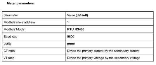
| parameter | Values (default) |
| Modbus slave address | From 1 to 247 (1) |
| Modbus Mode | RTU RS485 |
| Baud rate | 9600, 19200, 38400 (19200) |
| parity | Even, odd, none (even) |
| Maximum slave response time | 10 |
| CT ratio | Divide the primary current by the secondary current |
| VT ratio | Divide the primary voltage by the secondary voltage |
Overview
The Conext CL36 is a string inverter for commercial and industrial buildings, car ports, PV Diesel Hybrid and AC-coupled systems. The CL36 inverter communicates with Elum Explorer over Modbus communication protocol via its RS485 physical interface.
Installation steps
- Wire to Elum Explorer
- Set the Modbus Slave Address
Wiring to Elum Explorer
The location of the terminals on the communication card is shown below, where the Modbus RS485 connection can be wired through terminal connectors.

Connect the wires as shown in the following table:
| Elum Explorer Serial Port Terminal Block | Inverter Terminal Block |
| Pin | Pin |
| 3 | A |
| 4 | B |
| 5 | 0 |
The RS-485 bus is a multi-drop bus and can be implemented as a daisy chain as shown below. The RS485 Bus terminals and connectors are provided to ease the daisy chain connection. Either port can be connected to the upstream or downstream devices.

Setting the Modbus Slave Address
The Modbus slave address must be unique for each device on the Modbus network. The Modbus slave address may be read and/or modified via the Conext CL36 HMI. The Conext CL36 inverter address is selected using the menus shown below.

Overview
The PM2200 series are digital meters that offer 3-phase electrical instrumentation and load management facilities. Elum Explorer communicates with the PM2200 series over Modbus RTU.
Installation steps
- Wiring to Elum Explorer
- Configuration
Wiring to Elum Explorer
The RS-485 can be found on the bottom of the device.

Overview
The APM 403 is an instrumentation and control system for generating sets. APM 403 controllers communicate with Elum Explorer over Modbus TCP via a dedicated communication plug-in module.
Installation steps
- Plugging-in CM-Ethernet Modbus communication module
- Setting the CM-Ethernet parameters
- Wiring the inverters to Elum Explorer
Plugging-in CM-Ethernet Modbus communication module
CM-Ethernet is an optional plug-in card to enable APM to communicate over Modbus TCP using an Ethernet 10/100 Mbit interface in RJ45 connector.

The module is plugged into slot B located on the rear side of the controller, the procedure is as follows:
- Remove the back cover. To do this, press four holders which are located in the corners.
- Insert the plug-in module under holders marked by symbol 1. Then insert the plug-in module under holders marked by symbol 2.
- After locking the plug-in module into the holders, place back the back cover.

- Finally insert the small cover for the connectors. Small covers are unique for each plug-in module.

Check that slot B has been properly “occupied”. From the main screen, press twice to display the “Plug-in Modules” screen. The display must be as shown in the figure opposite (for slot B).

Accessing the CM-Ethernet parameters
To change any of the parameters of the CM-Ethernet module, the APM403 must be in “Advanced”
mode.
- From any measurement display screen, press


- Press four times
- Select “Advanced” mode using

- Press
Setting the CM-Ethernet communication parameters
- From the main screen, press
- Press
- Press
Overview
This guide supports 2 models of Kohler sdmo genset controller APM403P and APM403S. The communication protocol embedded is Modbus RTU using a half duplex 2 wires connection.
Installation steps
- Communication wiring
- Modbus setting
APM403 Connecting RS485 Communication Cables:
APM403 RS485 pinout:

| Pin | definition |
| A | RS485 Data + |
| Com | GND |
| B | RS485 Data – |
Connect multiple genset controllers in the Daisy Chain:
When connecting multiple equipments, the following procedure should be followed, as per the diagram (figure1.2):
- Connect the RS485 differential positive and negative signal of the explorer to terminal RS485 A and RS485 B of the first equipment.
- Connect terminal RS485 A and RS485 B of the first inverter in the daisy chain, to terminal RS485 A and RS485 B of other equipment.
- Repeat step 2 for all equipment on the same daisy chain.
- Terminate the daisy chain on both ends using 120 ohms termination resistors.


Overview
The MTR5LMOD is a power meter provided for the measurement and calculation of electrical parameters such as voltage, current, power, energy, etc. for building installations, to distributors, circuit breakers and busbar trunking systems.
The communication protocol embedded is Modbus RTU using a half duplex 2 wires connection.
Installation steps
- Communication wiring
- Modbus setting
Communication wiring:
MTR5LMOD RS485 pinout:

Connect multiple devices in a single Daisy Chain:
When connecting multiple types of equipment, the following procedure should be followed, as per the diagram (figure1.2):
- Connect the RS485 cable from the Elum unit terminal to the serial port of the first meter.
- Connect the RS485 cable from the first meter serial port to the second meter serial port.
- Repeat step 2 for all equipment on the same daisy chain.
- Terminate the daisy chain on both ends using 120 ohms termination resistors.

Overview
The UMG 96RM is provided for the measurement and calculation of electrical parameters such as voltage, current, power, energy, harmonics, etc. for building installations, to distributors, circuit breakers and busbar trunking systems. The communication protocol embedded is Modbus RTU using half duplex 2 wires connection.
Installation steps
- Communication wiring
- Modbus setting
Communication wiring:
UMG 96RM RS485 pinout:

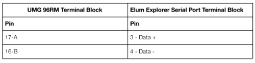
Connect multiple devices in a single Daisy Chain:
When connecting multiple equipment, the following procedure should be followed, as per the diagram (figure 2):
- Connect the RS485 differential positive and negative signal of the explorer to terminal A and B of the first power meter.
- Connect terminals A and B of the power meter in the daisy chain, to the terminal positive and negative signal of other equipment.
- Repeat step 2 for all equipment of the daisy chain.
- Add the matching resistor for the last piece of equipment.

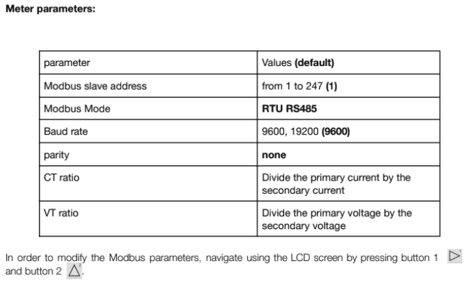
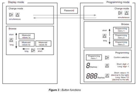
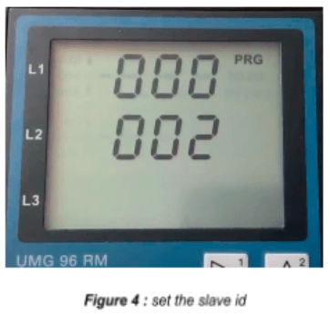
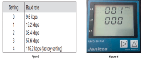
Modify the Slave ID and the baud rate
Install the ShinePhone APP here, and connect to inverter WIFI to enter the local monitoring page, this operation is performed by a professional.
➔ Click “Parameters”;
➔ Enter password.(When you use it for the first time, you need to set the password first. Click “Reset password” to enter the OSS account number and password. The distributor and installer can apply for the OSS account from Growatt. Click “Sign in” to set the password. After the setting is successful, you can start using it.)
➔ Click top item “COM Address”;
➔ Click the ” Read” button in the upper right corner to read the current communication address of the inverter;
➔ Set inverter com address;
➔ Read inverter com address to ensure setting is successful;


4. Connect the wires as shown in the following diagram:
| Elum Explorer Serial Port Terminal Block | X4 socket RS485-1 inverter |
| Pin | Pin |
| 3 | 2 |
| 5 | 5 |
| 4 | 7 |
5. Ground the connection: Connect terminal 5 on the inverter to the inverter housing using the
supplied flat strip connector.
6. If only one inverter is to be connected it must be terminated.
7. Put the supplied jumper onto the lower pins on the connector strip.

8. Close the inverter if no other inverters are to be connected.
9. Insert the terminal block connector into the Elum Explorer.
Connect the inverters to each other
1. Open the inverter as shown in the inverter’s instructions.
2. Connect the inverter in accordance with the inverter installation instructions.
3. If no further inverter is connected, terminate the inverter:
4. Put the supplied jumper onto the lower pins on the connector strip.
5. Close inverters.
Communication wiring:

Pin mapping to Elum Controller
❖ Remove the terminal block connector from the Elum serial port and connect the wires as
shown in the following table:
| Inverter Terminal Block | Elum Explorer Serial Port Terminal Block |
| Pin | Pin |
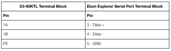
| 2 – D+ | 3 – Data + |
| 7 – D- | 4 – Data – |
| 5 – Ground | 5 – GND |
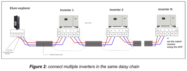
Connect multiple devices in a single Daisy Chain:
When connecting multiple equipment, the following procedure should be followed, as per the
diagram (figure 2):
- Connect the RS485 differential positive and negative signal of the explorer to pin 2 and 7 of the first inverter.
- Connect pins 2 and 7 of the first inverter in the daisy chain, to pins 2 and 7 of the following inverter.
- Repeat step 2 for all equipment on the same daisy chain.
- Terminate the daisy chain on both ends using 120 ohms termination resistors.

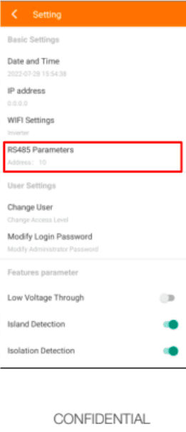
Setting the Inverter ID and communication parameters :
Inverter Parameters :
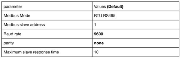
| Parameter | Values (Default) |
| Modbus Mode | RTU RS485 |
| Modbus slave address | From 1 to 247 (1) |
| Baud rate | 4800, 9600, 19200 (9600) |
| parity | None, odd, even (none) |
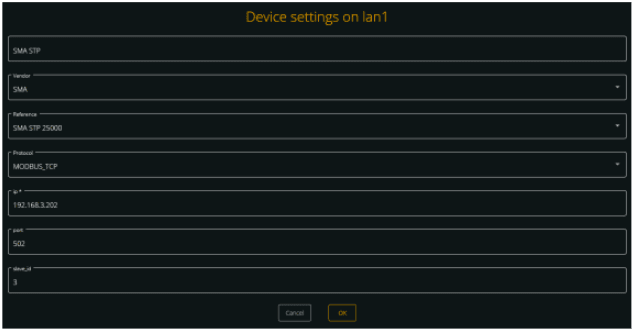
Modbus TCP :
– Ethernet connection :

– Modbus TCP setting :
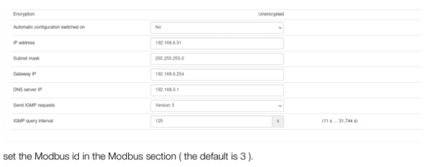
To connect a web browser to the product, Open the web browser of your smart device and enter the IP address 169.254.12.3 in the address bar.
The login page of the user interface opens.
Go to Device parameters and set the IP address in the External communication section.

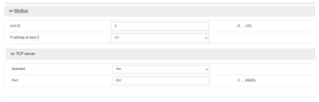
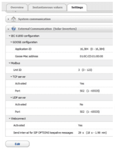
set the Modbus id in the Modbus section ( the default is 3 ).


Overview
The Sunny Tripower Core2 is a transformerless photovoltaic inverter which converts the direct current of the photovoltaic generator into grid-compliant three-phase current and feeds this into the public power grid.
Installation steps
- Ethernet | Modbus TCP

To connect a web browser to the product, Open the web browser of your smart device and enter the IP address 169.254.12.3 in the address bar.
The login page of the user interface opens.


Overview
The Sunny Tripower is a transformerless photovoltaic inverter with 6 MPP trackers which converts the direct current of the photovoltaic generator into grid-compliant three-phase current and feeds this into the public power grid.
The communication protocol embedded is Modbus RTU using half duplex 2 wires connection.
Installation steps
- RS485 | Modbus RTU
– Communication wiring
– Modbus setting
Communication wiring :
SMA RS485 pinout :

Pin mapping to Elum Controller
❖ Remove the terminal block connector from the Elum serial port and connect the wires as
shown in the following table:
| Inverter Terminal Block | Elum Explorer Serial Port Terminal Block |
| Pin | Pin |
| A | 3 – Data + |
| B | 4 – Data – |
| GND | 5 – GND |
Connect multiple devices in a single Daisy Chain:
When connecting multiple equipment, the following procedure should be followed, as per the
diagram (figure 2):
1. Connect the RS485 differential positive and negative signal of the explorer to pin A and B of
the first inverter.
2. Connect pins A and B of the first inverter in the daisy chain, to pins A and B of the following
inverter.
3. Repeat step 2 for all equipment on the same daisy chain.
4. Terminate the daisy chain on both ends using 120 ohms termination resistors.
Overview
The Sunny Tripower is a transformerless photovoltaic inverter with 6 MPP trackers which converts the direct current of the photovoltaic generator into grid-compliant three-phase current and feeds this into the public power grid.
The communication protocol embedded is Modbus RTU using half duplex 2 wires connection.
Installation steps
- RS485 | Modbus RTU
– Communication wiring
– Modbus setting
Communication wiring :
SMA RS485 pinout :
Pin mapping to Elum Controller
❖ Remove the terminal block connector from the Elum serial port and connect the wires as
shown in the following table:
| Inverter Terminal Block | Elum Explorer Serial Port Terminal Block |
| Pin | Pin |
| A | 3 – Data + |
| B | 4 – Data – |
| GND | 5 – GND |
Connect multiple devices in a single Daisy Chain:
When connecting multiple equipment, the following procedure should be followed, as per the diagram (figure 2):
- Connect the RS485 differential positive and negative signal of the explorer to pin A and B of the first inverter.
- Connect pins A and B of the first inverter in the daisy chain, to pins A and B of the following inverter.
- Repeat step 2 for all equipment on the same daisy chain.
- Terminate the daisy chain on both ends using 120 ohms termination resistors.

Setting the Inverter ID and communication parameters :
Inverter Parameters :
| Parameter | Values (Default) |
| Modbus Mode | RTU RS485 |
| Modbus slave address | From 1 to 247 (1) |
| Baud rate | 4800, 9600, 19200 (9600) |
| parity | None, odd, even (none) |
Modbus TCP :
– Ethernet connection :
– Modbus TCP setting :
To connect a web browser to the product, Open the web browser of your smart device and enter the IP address 169.254.12.3 in the address bar.
The login page of the user interface opens.
Go to Device parameters and set the IP address in the External communication section.
set the Modbus id in the Modbus section ( the default is 3 ).
Overview
The DIRIS B is a compact power meter with a modular format. It is designed for measuring, monitoring and reporting electrical energy. Diris B-30 RS communicates with Elum Explorer over Modbus RTU via an RS485 physical interface.
Installation steps
● Accessing the device for configuration
● Wiring to Elum Explorer
Accessing the device for configuration
Configuration can be carried out using the Easy Config configuration software or directly from the remote display.
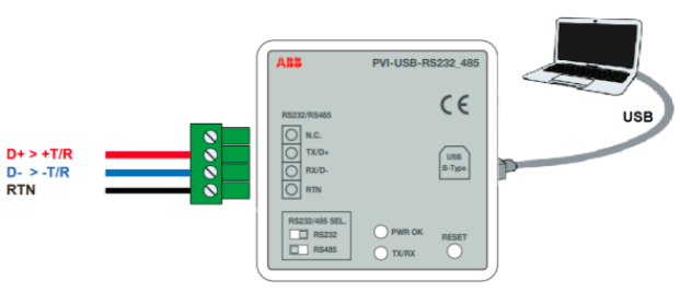
The Easy Config software is used to configure the DIRIS B directly via RS485 or USB. Easy Config must be installed before using the USB connection. The device should be connected to the computer as shown in the following figure:

The Easy Config is configuration software used to set product parameters. To connect the device to Easy Config, click Get from Device then Refresh USB Devices. The device detection will take place automatically.
Parameters are set in successive steps depending on the product:
Network —> Loads —> Measurement method —> Values to be stored —> Alarms —> End configuration
The RS484 Should be set as follows:
– Baud Rate: 9600 baud
– Modbus Slave address: according to Elum specifications
Wiring to Elum Explorer
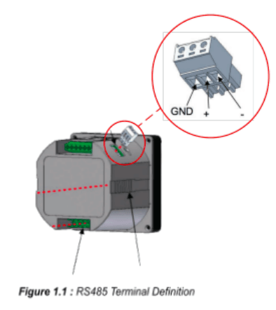
The RS485 interface location and specifications are shown in the following figure:

Wiring to Elum explorer should be done as follows:
| Elum Explorer Serial Port Terminal Block | Diris B30 RS Terminal block |
| Pin | Pin |
| 3 | + |
| 4 | – |
| 5 | NC |
⚠️ Important
It is essential to connect a resistance of 120 Ohms to the 2 ends of your RS485 network; this can be found in the product packaging.

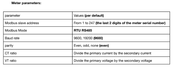
Setting Modbus parameters
Modbus parameters of the E43 meter should be set as follows:
● Address: Unique in the RS485 serial network (Range: 1 to 247)
● BaudRate: 9600 baud
● Parity: None
● STOP bit: 1
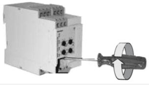
The procedure to access the parameters is the following:
- Use a screwdriver or any suitable object to press the PROG key for 5 seconds


- Press the PROG key 3 times to reach the first Modbus parameter which indicates the Modbus mode (Manual/Auto)


Use the prog key to navigate the parameters and the key above to change them.

The Modbus Parameters are structured as shown:

Installation steps
- Disconnect Studer equipment
- Open the Xcom 485i
- Selection of the PIN assignment of the RS-485 bus connection
- DIP switch setup (optional)
- Close the Xcom 485i
- Connect the Xcom485i to Studer equipment
- Connect the Xcom 485i to Elum Explorer
Disconnect Studer equipment
Disconnect your Xcom-485i module from all devices (installation, battery, etc.).
Open the Xcom 485i
1. Open the Xcom-485i with a screwdriver (2 screws).
2. On the electronic board inside the device there are two elements to select the chosen
configuration:
– Jumper array for RJ-45 (third party side) pinout arrangement.
– DIP switches to select a protocol-related configuration (see Modbus RTU Studer
protocol).

Selection of the PIN assignment of the RS-485 bus connection
To enable proper communication with Elum Explorer, the pin assignment of the Xcom485i must be done according to 2W Modbus described below:

DIP switch setup (optional)
The RS-485 baud rate can be selected using the dip switches 7 and 8 of the Xcom-485i. The
following tables show how to select it. If needed configure dip switches 7 and 8 according to your Communication Architecture Plan. The dip switches 1 to 6 should remain positioned on OFF.

Close the Xcom 485i with a screwdriver (2 screws).
Connect Xcom485i to Studer equipment
The Studer bus is daisy chained to the other XT/VT/VS Studer components and is powered by the communication plug as soon as the upfront device is powered. The Xcom-485i module should not be installed between 2 devices powered by the battery. Connect the Xcom-485i module with the supplied cable (2m). This cable should not be extended.

Connect the Xcom 485i to Elum Explorer
Most communication devices provide a specific connector and pin assignment. A specific cable has an RJ-45 connector on one side and on the other side, the third-party devices to a connector are required. This cable is either supplied by the manufacturer or must be crafted by the installer. The Xcom-485i package provides 2 cables with RJ-45 connectors on both ends. One of the two can be used to craft the proper cable.

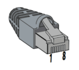
| Wire Color | Blue | Orange | Black | Red | Green | Yellow | Brown | White |
| Position Number | 1 | 2 | 3 | 4 | 5 | 6 | 7 | 8 |
| Modbus mapping | D-/B | D+/A | GND |
Connect the Xcom 485i to the Elum Explorer according to the described below wires Modbus
mapping and the Elum Explorer pin mapping described in the Elum User Manual.
Overview
Sungrow SG110CX is a transformerless three-phase PV grid-connected inverter. The SG110CX inverter could communicate with Elum Explorer over Modbus RTU communication protocol via two groups of RS485 physical interfaces. The following figure shows the position and the terminals of the inverter’s communication board.

When multiple inverters are connected in the RS485 daisy chain, a 120-ohms terminating resistor can be connected through the RS485 dip switch, to ensure communication quality.
Wiring to Elum Explorer
- Open the inverter according to the inverter‘s instructions.
- Pull the free wires through the wire opening in the inverter.
- Connect the wires as shown in the table and diagrams:

4. If no further inverter is connected, terminate the inverter
5. Close the inverter if no other inverters are to be connected.
6. Insert the terminal block connector into serial port 1 of Elum Explorer.
The RS485 connections on the terminal strip are each double connections so that the wiring can be continued to the next inverter.
When connecting multiple inverters, the connection should be performed as shown in the following diagram:

Overview
Colour Control is the communications center for Victron inverters in every type of application. Elum Explorer communicates with Victron inverters through the Colour Control over Ethernet | Modbus TCP or MQTT.
Installation steps
- Configuration
- Wiring to Elum Explorer
- Setup on Elum Configuration
Configuration
- Navigate to the settings/ethernet menu
- Set the IP configuration to Manual, and note all the network configuration parameters (IP address, Netmask, Gateway, DNS) on the deployment form.
- Navigate to Settings/Services
- Activate the Modbus/TCP functionality
- Activate the VRM Two-Way


Connection to Elum Explorer

Connect the LAN1 port of the Elum Explorer to the Ethernet port of the Victron Color Control.
Setup on Elum Configuration
When adding the Color Control on Elum Configuration, you must indicate slave_id: 100

Overview
The Venus GX (VGX) and the Color Control GX (CCGX) have the functionality and run on the same software, the “Venus OS”. The Venus GX is more cost-effective and offers more analog and digital inputs and outputs. However, the latter is not equipped with a local monitoring and configuration interface, therefore a smartphone, tablet, or laptop is required to access the device’s Remote Console.
Installation steps
- Access to remote console
- Configuration
- Wiring to Elum Explorer
- Setup on Elum Configuration
Access to remote console
The easiest way to access the Venus GX Remote Console is by using the built-in WiFi Access Point. The steps are as follows:
- Make sure you are no further than a few meters away from the Venus GX
- Go to the WiFi settings on your phone/tablet/laptop.
- After searching, the Venus GX will show up in the list, as Venus- the serial number as printed on the box-.
- Connect to WiFi using the ‘WiFi key’ which you will find printed on the side of the box and also on a card in the plastic bag.
- Once connected, the Remote Console can be accessed by inserting the IP address 172.24.24.1 in a web browser.
- Use the hotkeys to navigate the console

- Configuration Navigate to the settings/ethernet menu
- Set the IP configuration to Manual, and note all the network configuration
parameters (IP address, Netmask,Gateway, DNS) on the deployment form. - Navigate to Settings/Services
- Activate the Modbus/TCP functionality
- Activate the VRM Two-Way Communication
- Activate the MQTT functionality


Wiring to Elum Explorer
Connect the LAN1 port of the Elum Explorer to the Ethernet port at the bottom of the Victron
Venus GX.

Setup on Elum Configuration
When adding the Color Control on Elum Configuration, you must indicate slave_id: 100

Overview
The Wes module allows the collection of data and pilot several devices (power meters, temperature sensors …) through Modbus TCP protocol using RJ 45 wires.

Installation steps
- Wiring to Elum Explorer
- Setting a static IP address
- Set the I/O parameters
Wiring to Elum Explorer
Connect the RJ45 port located near the power supply LED with a LAN wire, to the LAN port 1 on
the Elum Explorer
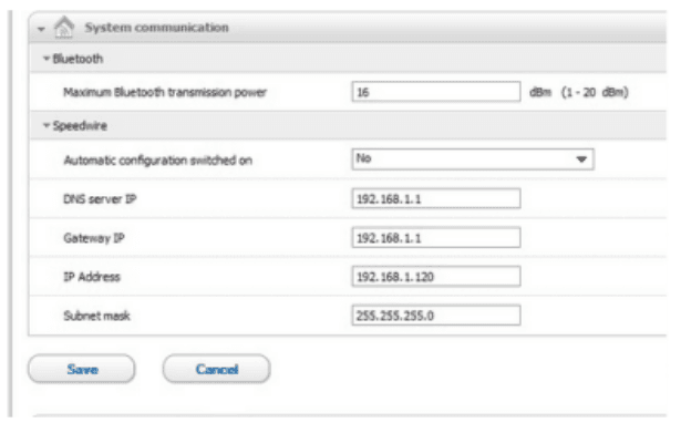
Modbus TCP Configuration
To allow communication with the device, you must configure on the Elum configuration interface the LAN 1 port as follows:
– Static Ip: 192.168.1.1
– Subnet Mask: 255.255.255.0
– Host: 192.168.1.100
– port: 80
– Gateway & DNS: leave it blank
Set the I/O parameters
– WES, Temperature: ID

Each sensor has a unique ID that is noted on the bar code tag on the wire close to the RJ11 connector, as shown in the picture below.

For example, this temperature sensor has an ID: 28AAF0B74F1401, note that spaces and capital letters are not important.
Device Connection & Configuration Specific Instructions
– WES, Wattmeter and TIC Wattmeter: Convention

The “Active” Convention must be applied on the meters that are measuring production. The
“Passive” convention must be set for meters measuring consumption.
– WES, Wattmeter: Pulse

Define the right meter ratio, Wh/Impulsion.
– WES, Irradiance: Scale

The scale factor to be applied is expressed in W/m²/V. Further information on this part can be found in the manufacturer’s documentation of the irradiance sensor.
Overview
easYgen-3000 Controls are the generator set digital paralleling controls responsible for synchronizing, load sharing, protection, metering and monitoring suitable for any power system application needs.
The communication protocol embedded is Modbus RTU using half duplex 2 wires connection.
Installation steps
● Communication wiring
● Modbus setting
Communication wiring :
easYgen-3000 RS485 pinout :

Pin mapping to Elum Controller
❖ Remove the terminal block connector from the Elum serial port and connect the wires as
shown in the following table:
| easYgen-3000 Terminal Block | Elum Explorer Serial Port Terminal Block |
| Pin | Pin |
| 5 | 3 – Data + |
| 6 | 4 – Data – |
Connect multiple genset controllers in the Daisy Chain:
When connecting multiple genset controllers, the following procedure should be followed:
- Connect the RS485 differential positive and negative signal of the explorer to terminal 5
and 6 of the first equipment. - Connect terminal 5 and 6 of the first inverter in the daisy chain, to terminal 5 and 6 of other equipment.
- Repeat step 2 for all equipment on the same daisy chain.
- Terminate the daisy chain on both ends using 120 ohms termination resistors.

Genset controller parameters:
| parameter | Values (default) |
| Modbus slave address | From 1 to 255 (1) |
| Modbus Mode | RTU RS485 |
| Baud rate | 9600 / 19200 / 38400 / 57600 / 115200 (19200) |
| parity | Even, odd none (none) |
Overview
SOFAR 80~136KTL is a transformerless on grid PV inverter, that converts the direct current of the PV array to the grid-compliant, three-phase current and feeds into the utility grid. The communication protocol embedded is Modbus RTU using half duplex 2 wires connection.
Installation steps
- Communication wiring
- Modbus setting
Communication wiring :

Pin mapping to Elum Controller
❖ Remove the terminal block connector from the Elum serial port and connect the wires as
shown in the following table:
| Inverter Terminal Block | Elum Explorer Serial Port Terminal Block |
| Pin | Pin |
| 1 – RS485A | 3 – Data + |
| 3 – RS485B | 4 – Data – |
Connect multiple devices in a single Daisy Chain:
When connecting multiple equipment, the following procedure should be followed, as per the
diagram (figure 2):
- Connect the RS485 cable from the Elum unit terminal to the serial port of the first inverter.
- Connect the RS485 cable from the first inverter serial port to the second inverter serial port.
- Repeat step 2 for all equipment on the same daisy chain.
- Terminate the daisy chain on both ends using 120 ohms termination resistors.

Setting the Inverter ID and communication parameters :
Inverter Parameters :
| parameter | Values (Default) |
| Modbus Mode | RTU RS485 |
| Modbus slave address | 1~247 (1) |
| Baud rate | 4800, 9600, 19200, 38400, 57600, 115200, 1200, 2400 (9600) |
| parity | None, even, odd (none) |
Modify the inverter address :
- Long press the down button under the standard interface to enter into the main interface.
- Enter setting Interface by long pressing the do down button.
- Scroll to the option 7 and long press the Down button, then set the new id.
