Homepage > Elum Academy > Elum Academy: ePowerControl MC Series
ePowerControl MC Series
Unlock full training resources designed to ensure smooth system setup and operation.
Getting started
Get started with our in-depth training course, guiding you through every step of the installation process.
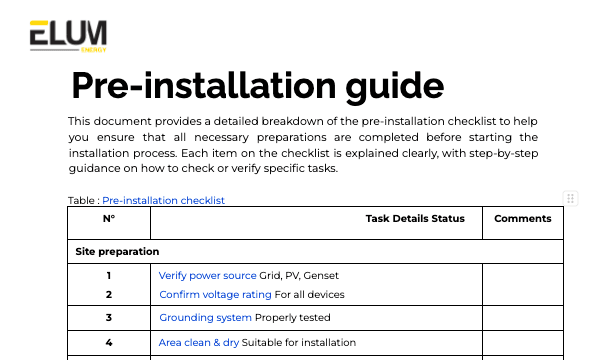
- Lessons 1 & 2: Pre-installation essentials, required tools, and everything you need to get started.
- Lessons 3–7: Step-by-step installation, setup, and configuration of ePowerControl MC.
For extra help, visit the troubleshooting section for detailed solutions and support.
Course Structure
Objective:
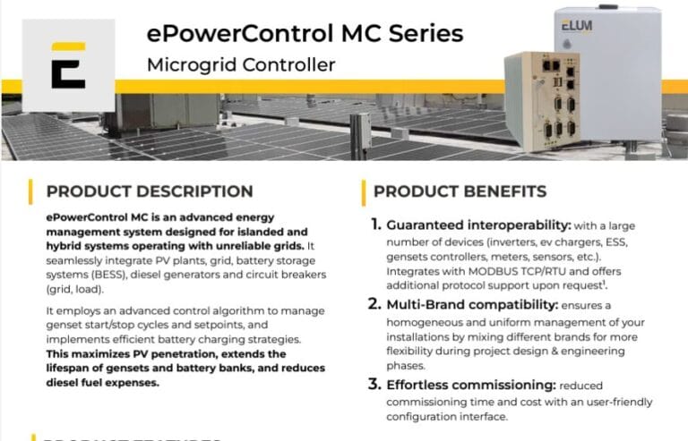
Understand the role of ePowerControl MC: Gain a comprehensive understanding of the ePowerControl MC, focusing on its function in managing complex microgrids with PV, grid, battery storage, and diesel generators to maximize efficiency, minimize fuel usage, and ensure reliable system operation in hybrid or islanded modes.
Content:
Overview of ePowerControl MC: Key features include advanced microgrid control, seamless integration with multiple devices, multi-mode energy management (Grid, BESS, and Genset Prime Modes), dynamic battery and genset management, reactive power regulation, robust data logging, and remote monitoring capabilities for comprehensive hybrid system oversight.
Objective:
Prepare for installation: Ensure you have all the required tools, equipment, and knowledge to successfully complete the physical installation of ePowerControl MC, ensuring a smooth and efficient setup for your hybrid microgrid system.
Content:
Objective:
Installation and internet setup: Learn how to physically install the ePowerControl MC series and configure the internet connection to ensure reliable remote access and seamless monitoring functionality.
Video Step-by-Step Instructions:
Installation of ePowerControl MC
Objective:
Meter connections: Follow a step-by-step guide on connecting meters to the Elum unit using Modbus TCP (Ethernet) and Modbus RTU (Serial) to enable accurate energy monitoring.
Video Step-by-Step Instructions:
Meters connection - Modbus TCP (Ethernet) & Modbus RTU (Serial)
Reference Material
Please consult our compatibility device evaluator for additional information.: https://elum-energy.com/compatibility/
Objective:
PV inverter connections: Learn the process of connecting PV inverters using Modbus TCP and Modbus RTU for efficient data exchange in solar power monitoring.
Video Step-by-Step Instructions:
PV inverters connection - Modbus TCP (Ethernet) & Modbus RTU (Serial)
Reference Material
Please consult our compatibility device evaluator for additional information.: https://elum-energy.com/compatibility/
Objective:
Genset controller connections: Learn the steps to connect genset controllers to the Elum unit via Modbus TCP and Modbus RTU, enabling reliable backup power monitoring. accurate energy monitoring.
Video Step-by-Step Instructions:
Genset controllers connection - Modbus TCP (Ethernet) & Modbus RTU (Serial)
Reference Material
Please consult our compatibility device evaluator for additional information.: https://elum-energy.com/compatibility/
Objective:
Sensors configuration: Understand how to set up a range of sensors on the Elum unit using Modbus TCP and Modbus RTU, ensuring comprehensive system data collection
Video Step-by-Step Instructions:
Sensors connection - Modbus TCP (Ethernet) & Modbus RTU (Serial)
Reference Material
Please consult our compatibility device evaluator for additional information.: https://elum-energy.com/compatibility/
Troubleshooting ePowerControl MC
Enhance troubleshooting proficiency: Gain the knowledge needed to effectively diagnose and resolve common issues in hybrid energy systems, enhancing system reliability and performance.
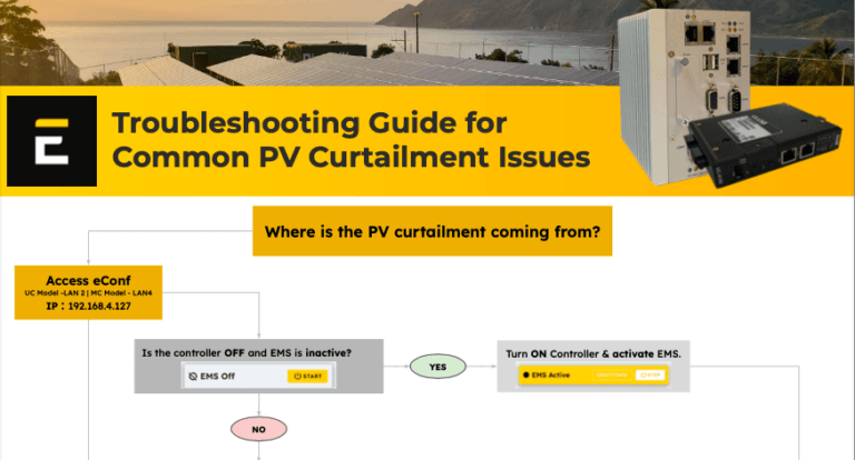
Overview of troubleshooting protocols: Key methods for resolving communication errors, addressing PV curtailment, verifying Modbus configurations, and ensuring accurate system settings in eConf.