Homepage > Elum Academy > Elum Academy: ePowerControl ZE series
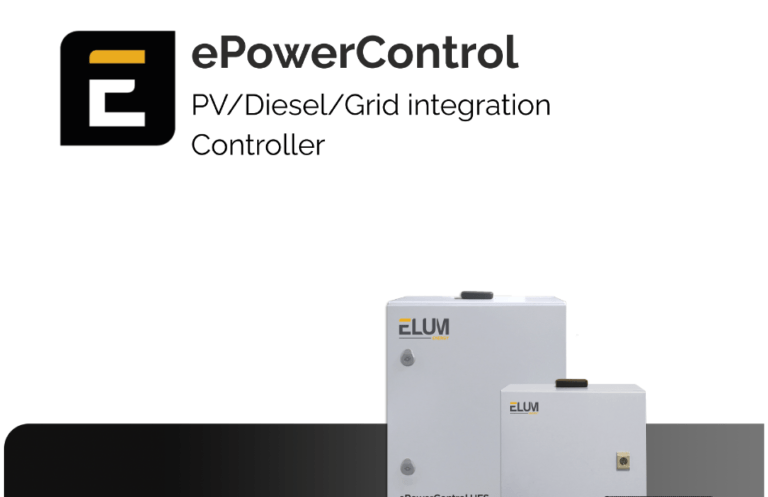
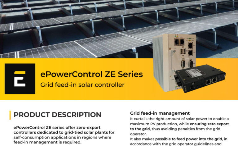
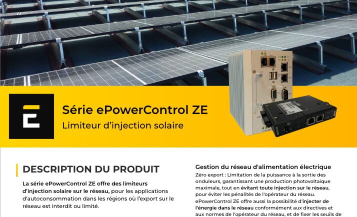
ePowerControl ZE series
Select your solution's series code to begin

- Perfect for installers looking to understand the foundational installation process
- For users who want to learn from training that covers all essential steps to get your system up and running smoothly
Training Course: ePowerControl ZE 500 & 1000
Get started with our in-depth training course, guiding you through every step of the installation process.
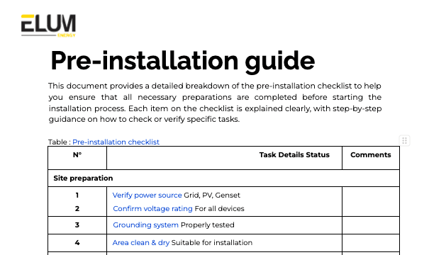
- Lessons 1 & 2: Pre-installation essentials, required tools, and everything you need to get started.
- Lessons 3–7: Step-by-step installation, setup, and configuration of ePowerControl ZE series.
For extra help, visit the troubleshooting section for detailed solutions and support.
Course Structure
Objective:
Understand the role of ePowerControl ZE500 & ZE1000: Gain a comprehensive understanding of the ePowerControl ZE, focusing on its application in managing grid feed-in restrictions and ensuring regulatory compliance in solar installations.
Content:
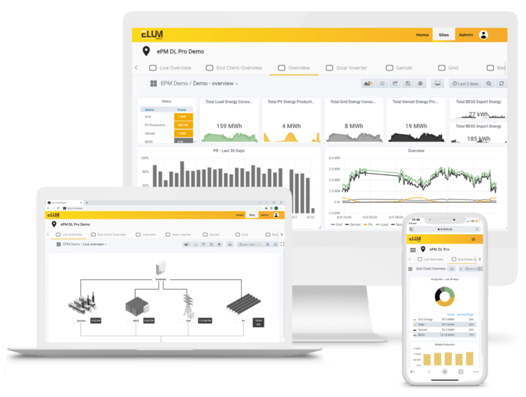
Overview of ePowerControl ZE500 & ZE1000: Key zero-export features, compatibility with diverse inverter brands, flexible feed-in management options, data logging, and remote monitoring capabilities.
Objective:
Prepare for installation: Ensure you have all the required tools, equipment, and knowledge to successfully carry out the physical installation of ePowerControl ZE, enabling a smooth and efficient setup.
Objective:
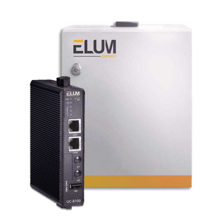
Installation and internet setup: Learn how to physically install the ePowerControl ZE500 & ZE1000 and configure the internet connection to enable reliable remote access and seamless monitoring functionality.
Video Step-by-Step Instructions:
Installation of ePowerControl HFS-S
Objective:
Meter connections: Follow a step-by-step guide on connecting meters to the Elum unit using Modbus TCP (Ethernet) and Modbus RTU (Serial) to enable accurate energy monitoring.
Video Step-by-Step Instructions:
Meters connection - Modbus TCP (Ethernet) & Modbus RTU (Serial)
Reference Material
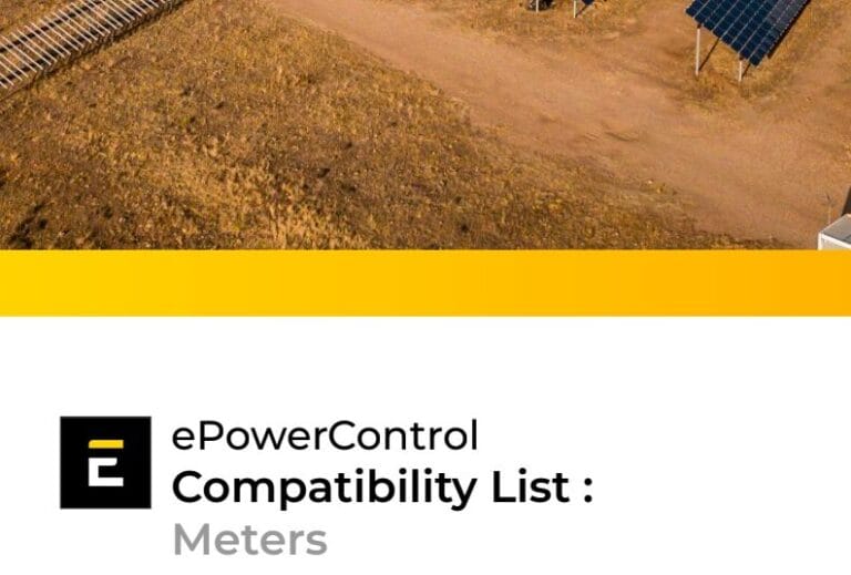
Please consult our compatibility device evaluator for additional information.
Objective:
PV inverter connections: Learn the process of connecting PV inverters using Modbus TCP and Modbus RTU for efficient data exchange in solar power monitoring.
Video Step-by-Step Instructions:
PV inverters connection - Modbus TCP (Ethernet) & Modbus RTU (Serial)
Reference Material
Please consult our compatibility device evaluator for additional information.
Objective:
Genset controller connections: Learn the steps to connect genset controllers to the Elum unit via Modbus TCP and Modbus RTU, enabling reliable backup power monitoring.
Video Step-by-Step Instructions:
Genset controllers connection - Modbus TCP (Ethernet) & Modbus RTU (Serial)
Reference Material
Please consult our compatibility device evaluator for additional information.: https://elum-energy.com/compatibility/
Objective:
Sensors configuration: Understand how to set up a range of sensors on the Elum unit using Modbus TCP and Modbus RTU, ensuring comprehensive system data collection
Video Step-by-Step Instructions:
Sensors connection - Modbus TCP (Ethernet) & Modbus RTU (Serial)
Reference Material
Please consult our compatibility device evaluator for additional information.: https://elum-energy.com/compatibility/
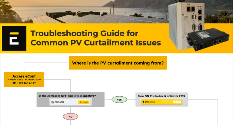
Troubleshooting ZE500 & ZE1000
Enhance troubleshooting proficiency: Gain the knowledge needed to effectively diagnose and resolve common issues in hybrid energy systems, enhancing system reliability and performance.
Overview of troubleshooting protocols: Key methods for resolving communication errors, addressing PV curtailment, verifying Modbus configurations, and ensuring accurate system settings in eConf.

Training Course: ePowerControl ZE3000
Get started with our in-depth training course, guiding you through every step of the installation process.
- Lessons 1 & 2: Pre-installation essentials, required tools, and everything you need to get started.
- Lessons 3–7: Step-by-step installation, setup, and configuration of ePowerControl ZE3000.
For extra help, visit the troubleshooting section for detailed solutions and support.
Course Structure
Objective:
Understand the role of ePowerControl ZE3000: Gain a comprehensive understanding of the ePowerControl ZE3000, focusing on its application in managing grid feed-in restrictions, reactive power regulation, and ensuring regulatory compliance in large-scale solar installations.
Content:
Overview of ePowerControl ZE3000: Advanced zero-export features, broad compatibility with various inverter brands, flexible feed-in management options, secure data logging, and robust remote monitoring capabilities tailored for large-scale solar installations.
Objective:
Prepare for installation: Ensure you have all the required tools, equipment, and knowledge to successfully carry out the physical installation of ePowerControl ZE, enabling a smooth and efficient setup.
Content:
Objective:
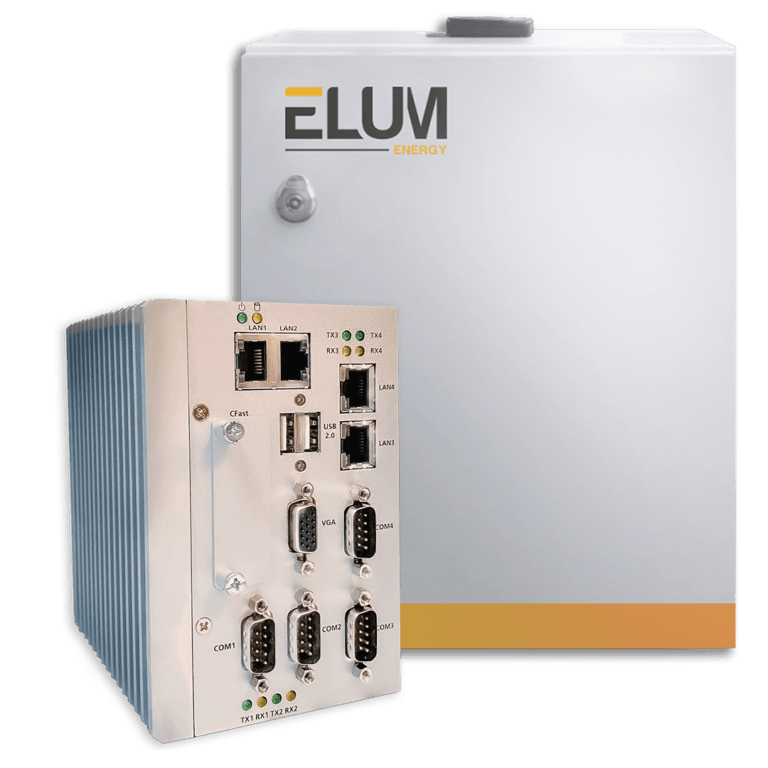
Installation and internet setup: Learn how to physically install the ePowerControl ZE3000 and configure the internet connection to enable reliable remote access and seamless monitoring functionality.
Video Step-by-Step Instructions:
Installation of ePowerControl HFS-S & HFS-L
Objective:
Meter connections: Follow a step-by-step guide on connecting meters to the Elum unit using Modbus TCP (Ethernet) and Modbus RTU (Serial) to enable accurate energy monitoring.
Video Step-by-Step:
Meters connection - Modbus TCP (Ethernet) & Modbus RTU (Serial)
Reference Material
Please consult our compatibility device evaluator for additional information.
Objective:
PV inverter connections: Learn the process of connecting PV inverters using Modbus TCP and Modbus RTU for efficient data exchange in solar power monitoring.
Video Step-by-Step:
PV inverters connection - Modbus TCP (Ethernet) & Modbus RTU (Serial)
Reference Material
Please consult our compatibility device evaluator for additional information.
Objective:
Genset controller connections: Learn the steps to connect genset controllers to the Elum unit via Modbus TCP and Modbus RTU, enabling reliable backup power monitoring.
Video Step-by-Step:
Genset controllers connection - Modbus TCP (Ethernet) & Modbus RTU (Serial)
Reference Material
Please consult our compatibility device evaluator for additional information.
Objective:
Sensors configuration: Understand how to set up a range of sensors on the Elum unit using Modbus TCP and Modbus RTU, ensuring comprehensive system data collection
Video Step-by-Step:
Sensors connection - Modbus TCP (Ethernet) & Modbus RTU (Serial)
Reference Material
Please consult our compatibility device evaluator for additional information
Troubleshooting ZE3000
Enhance troubleshooting proficiency: Gain the knowledge needed to effectively diagnose and resolve common issues in hybrid energy systems, enhancing system reliability and performance.
Overview of troubleshooting protocols: Key methods for resolving communication errors, addressing PV curtailment, verifying Modbus configurations, and ensuring accurate system settings in eConf.